FRONT DOOR DISASSEMBLY

Tech Tips
-
Use the same procedure for the RH and LH sides.
-
The procedure listed below is for the LH side.
-
PRECAUTION
Note
After turning the power switch off, waiting time may be required before disconnecting the cable from the auxiliary battery terminal. Therefore, make sure to read the disconnecting the cable from the auxiliary battery terminal notice before proceeding with work Click here.
-
REMOVE LUGGAGE COMPARTMENT FLOOR MAT
-
Remove the luggage compartment floor mat.
-
-
REMOVE LUGGAGE COMPARTMENT TRIM COVER LH
-
Remove the luggage compartment trim cover LH.
-
-
DISCONNECT CABLE FROM AUXILIARY BATTERY NEGATIVE TERMINAL
CAUTION:
Wait at least 90 seconds after disconnecting the cable from the negative (-) auxiliary battery terminal to disable the SRS system.
Note
When disconnecting the cable, some systems need to be initialized after the cable is reconnected Click here.
-
REMOVE POWER WINDOW REGULATOR MASTER SWITCH ASSEMBLY WITH FRONT DOOR ARMREST BASE PANEL
-
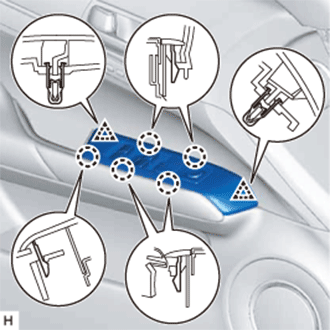
Detach the 2 clips and 5 claws.
-
Disconnect the connector and remove the power window regulator master switch assembly with front door armrest base panel.
-
-
REMOVE FRONT DOOR INSIDE HANDLE BEZEL PLUG LH
-
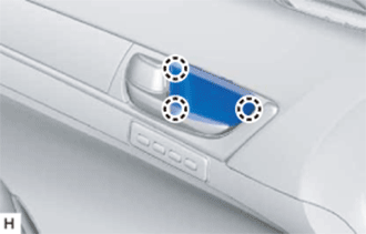
Detach the 3 claws and remove the front door inside handle bezel plug.
-
-
REMOVE COURTESY LIGHT ASSEMBLY
-
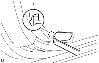
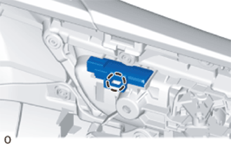
Using a moulding remover A, detach the claw and remove the courtesy light assembly.
-
Disconnect the connector.
-
-
REMOVE FRONT DOOR HOLE COVER
-
Remove the front door hole cover.
-
-
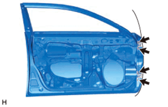
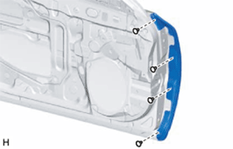
REMOVE FRONT DOOR TRIM BOARD SUB-ASSEMBLY LH
-
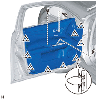
Remove the 3 screws.
-
Detach the 9 clips.
-
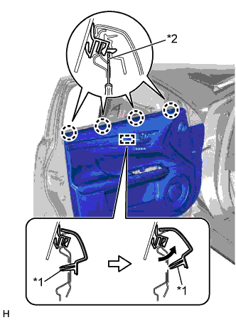
Detach the reference boss in the direction indicated by the arrow in the illustration.
-
Using a screwdriver, detach the 4 claws and remove the front door trim board.
Tech Tips
Tape the screwdriver tip before use.
Text in Illustration *1 Reference Boss *2 Protective Tape -
Disconnect each connector.
-
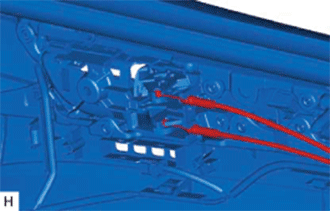
Disconnect the front door lock remote control cable and front door inside locking cable.
-
-
REMOVE SWITCH BEZEL
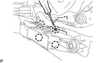
Text in Illustration *1 Protective Tape
-
Using a screwdriver, detach the 4 claws and remove the switch bezel from the seat memory switch.
Tech Tips
Tape the screwdriver tip before use.
-
-
REMOVE SEAT MEMORY SWITCH
-
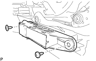
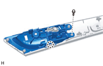
Remove the 2 screws and seat memory switch from the front door trim board sub-assembly LH.
-
-
REMOVE FRONT DOOR INSIDE HANDLE ILLUMINATION LIGHT ASSEMBLY LH
-
Detach the claw and remove the front door inside handle illumination light assembly LH.
-
Disconnect the connector.
-
-
REMOVE FRONT DOOR INSIDE HANDLE SUB-ASSEMBLY LH
-
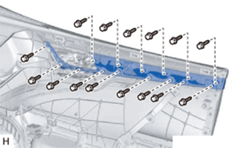
Remove the 15 screws and front door inside handle together with the front door trim ornament and No. 1 interior illumination light.
-
Remove the screw.
-
Detach the claw and remove the front door inside handle.
-
-
REMOVE FRONT DOOR TRIM ORNAMENT SUB-ASSEMBLY LH
-
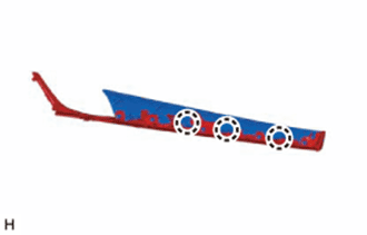
Detach the 3 claws and remove the front door trim ornament from the No. 1 interior illumination light.
-
-
REMOVE FRONT DOOR TRIM SEAL LH
-
Detach the 11 clips and remove the front door trim seal.
-
-
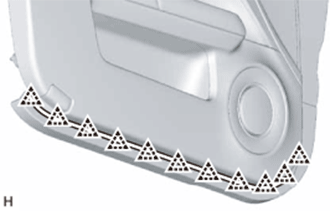
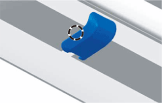
REMOVE FRONT DOOR NO. 1 STIFFENER CUSHION
-
Remove the front door No. 1 stiffener cushion.
-
-
REMOVE FRONT DOOR TRIM COVER LH
-
Detach the 5 clips and remove the front door trim cover.
-
-
REMOVE DOOR FRAME GARNISH LH
-
Detach the 2 clips and remove the door frame garnish.
-
-
REMOVE FRONT DOOR INNER GLASS WEATHERSTRIP LH
-
Remove the front door inner glass weatherstrip.
-
-
REMOVE FRONT DOOR ARMREST SET BRACKET LH
-
Remove the 2 screws and front door armrest set bracket.
-
-
REMOVE FRONT DOOR SERVICE HOLE COVER LH
-
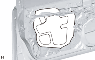
Pull out the front door lock remote control cable and front door inside locking cable from the front door service hole cover, and then remove the front door service hole cover.
Tech Tips
Remove any remaining butyl tape from the front door panel.
-
-
REMOVE FRONT DOOR NO. 2 SERVICE HOLE COVER LH
-
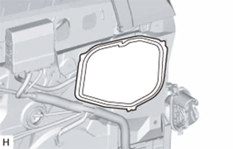
Remove the front door No. 2 service hole cover.
Tech Tips
Remove any remaining butyl tape from the front door panel.
-
-
REMOVE FRONT NO. 1 SPEAKER ASSEMBLY
-
Disconnect the connector.
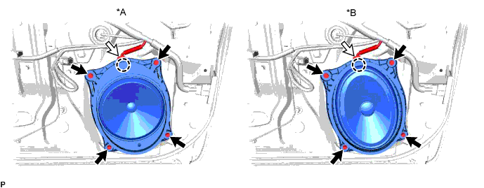
Text in Illustration *A w/o Mark Levinson Speaker System *B w/ Mark Levinson Speaker System -
Remove the 4 screws.
-
Detach the claw and remove the front No. 1 speaker assembly.
Note
Do not touch the cone of the speaker.
-
-
REMOVE FRONT DOOR GLASS SUB-ASSEMBLY LH
-
Temporarily install the power window regulator master switch assembly with front door armrest base panel.
-
Connect the cable to the negative (-) auxiliary battery terminal.
-
Move the front door window regulator so that the front door glass bolts can be seen.
-
Disconnect the cable from the negative (-) auxiliary battery terminal.
Note
When disconnecting the cable, some systems need to be initialized after the cable is reconnected Click here.
-
Remove the power window regulator master switch assembly with front door armrest base panel.
-
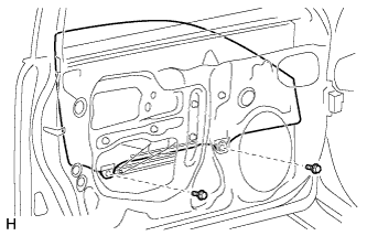
Remove the 2 bolts.
Note
After the bolts are removed, do not allow the front door glass to fall.
-
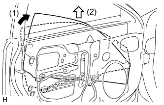
Remove the front door glass as indicated by the arrows in the order shown in the illustration.
Note
Do not damage the front door glass.
-
-
REMOVE FRONT DOOR GLASS RUN LH
-
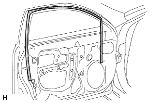
Remove the front door glass run.
-
-
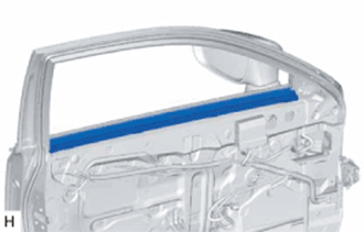
REMOVE FRONT DOOR BELT MOULDING ASSEMBLY LH
-
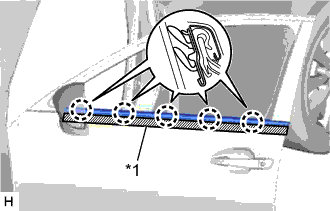
Text in Illustration *1 Protective Tape Put protective tape around the front door belt moulding.
-
Detach the 5 claws and remove the front door belt moulding.
-
-
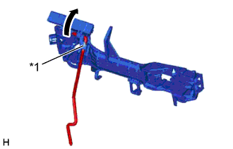
REMOVE FRONT DOOR WINDOW REGULATOR SUB-ASSEMBLY LH
-
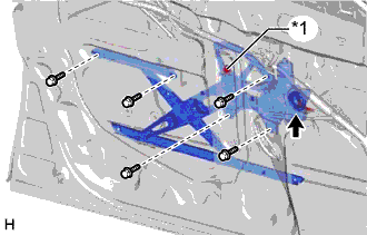
Text in Illustration *1 Temporary Bolt Disconnect the connector.
-
Loosen the temporary bolt.
Note
Do not remove the temporary bolt. If the temporary bolt is removed, the front door window regulator may fall and become damaged.
-
Remove the 5 bolts and front door power window regulator.
-
Remove the temporary bolt from the front door window regulator.
-
-
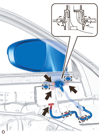
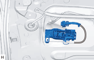
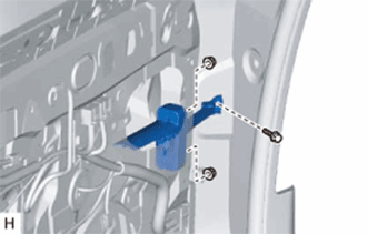
REMOVE FRONT MULTIPLEX NETWORK DOOR ECU LH
-
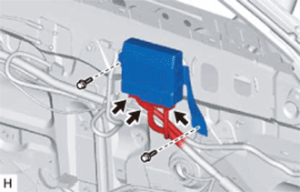
Disconnect the 3 connectors.
-
Remove the 2 bolts and front multiplex network door ECU.
-
-
REMOVE OUTER MIRROR PROTECTOR
-
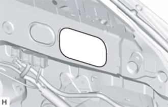
Remove the outer mirror protector.
-
-
REMOVE OUTER REAR VIEW MIRROR ASSEMBLY LH
-
Disconnect the connector.
-
Using a clip remover, detach the 2 clamps.
-
Remove the 3 nuts.
-
Detach the 2 claws and remove the outer rear view mirror assembly LH.
-
-
REMOVE FRONT DOOR REAR LOWER FRAME SUB-ASSEMBLY LH
-
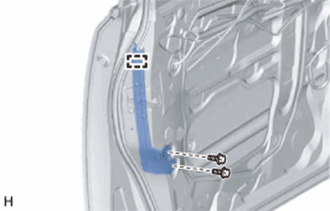
Remove the 2 bolts.
-
Detach the guide and remove the front door rear lower frame.
-
-
REMOVE FRONT DOOR NO. 2 STIFFENER CUSHION
-
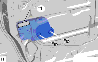
Text in Illustration *1 Double-sided Tape Remove the 2 bolts.
-
Remove the double-sided tape and front door No. 2 stiffener cushion.
-
-
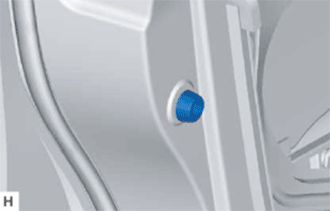
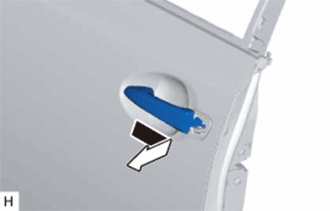
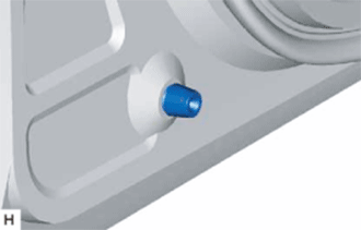
REMOVE FRONT DOOR OUTSIDE HANDLE COVER LH
-
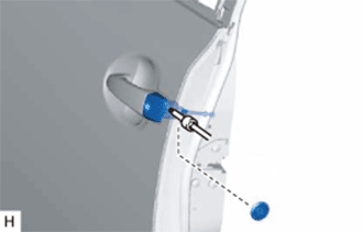
Remove the hole plug.
-
Using a T30 "TORX" socket wrench, loosen the screw and remove the front door outside handle cover together with the front door lock cylinder.
-
-
REMOVE FRONT DOOR LOCK CYLINDER ASSEMBLY
-
Detach the 2 claws and remove the front door lock cylinder from the front door outside handle cover.
-
-
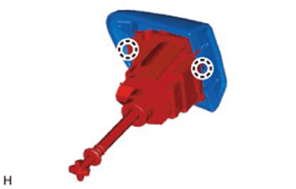
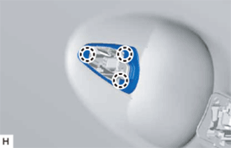
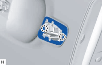
REMOVE FRONT DOOR LOCK ASSEMBLY LH
-
Disconnect the connector.
-
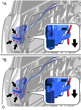
Text in Illustration *A w/o Double Locking System *B w/ Double Locking System Using a T30 "TORX" socket wrench, remove the 3 screws.
-
Slide the front door lock assembly downward, and remove the front door lock assembly and cables as a unit.
-
Remove the door lock wiring harness seal from the front door lock assembly.
-
-
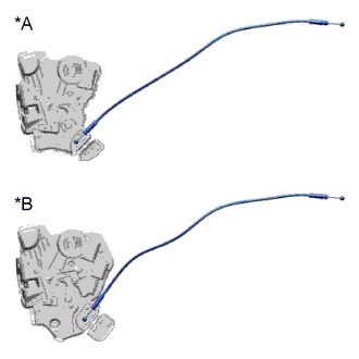
REMOVE FRONT DOOR LOCK REMOTE CONTROL CABLE ASSEMBLY LH
-
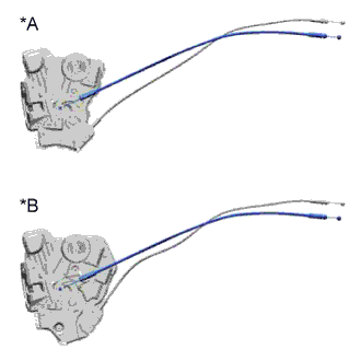
Text in Illustration *A w/o Double Locking System *B w/ Double Locking System Remove the front door lock remote control cable.
-
-
REMOVE FRONT DOOR INSIDE LOCKING CABLE ASSEMBLY LH
-
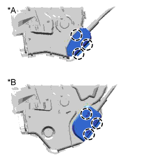
Text in Illustration *A w/o Double Locking System *B w/ Double Locking System Detach the 3 claws and open the cover.
-
Text in Illustration *A w/o Double Locking System *B w/ Double Locking System Remove the front door inside locking cable.
-
-
REMOVE FRONT DOOR OUTSIDE HANDLE ASSEMBLY LH
-
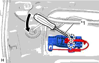
Text in Illustration *1 Protective Tape Using a screwdriver, detach the 2 claws of the connector cover in the direction indicated by the arrow in the illustration and disconnect the connector cover.
Tech Tips
Tape the screwdriver tip before use.
-
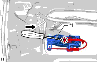
Text in Illustration *1 Protective Tape Using a screwdriver, detach the claw of the connector in the direction indicated by the arrow in the illustration and disconnect the connector.
Tech Tips
Tape the screwdriver tip before use.
-
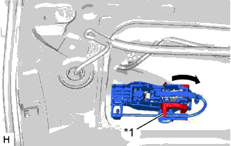
Text in Illustration *1 Holder Detach the holder in the direction indicated by the arrow in the illustration.
-
Remove the front door outside handle by sliding and pulling it in the direction indicated by the arrow in the illustration.
-
-
REMOVE FRONT DOOR FRONT OUTSIDE HANDLE PAD
-
Detach the 3 claws and remove the front door front outside handle pad.
-
-
REMOVE FRONT DOOR REAR OUTSIDE HANDLE PAD
-
Detach the 2 claws and remove the front door rear outside handle pad.
-
-
REMOVE FRONT DOOR OUTSIDE HANDLE FRAME SUB-ASSEMBLY LH
-
Using a T30 "TORX" socket wrench, loosen the screw and front door outside handle frame.
-
Detach the 2 clamps of the front door wire.
-
-
REMOVE FRONT DOOR LOCK OPEN ROD LH
-
Text in Illustration *1 Snap Rotate the snap in the direction indicated by the arrow in the illustration to detach the snap from the front door lock open rod.
-
Remove the front door lock open rod from the front door outside handle frame.
-
-
REMOVE FRONT DOOR NO. 2 WEATHERSTRIP LH
-
Detach the 9 clips and remove the front door No. 2 weatherstrip.
-
-
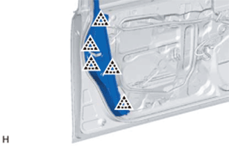
REMOVE FRONT DOOR PANEL CUSHION
-
Remove the front door panel cushion.
-
-
REMOVE FRONT DOOR DUST PROOF SEAL
Tech Tips
Use the same procedure for all front door dust proof seals.
-
Detach the claw and remove the front door dust proof seal.
-
-
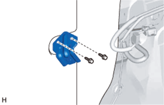
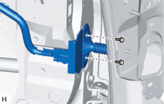
REMOVE FRONT DOOR CHECK ASSEMBLY LH
-
Remove the bolt, 2 nuts and front door check.
-
-
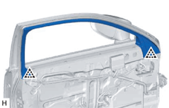
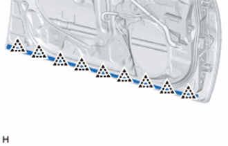
REMOVE FRONT DOOR WEATHERSTRIP LH
-
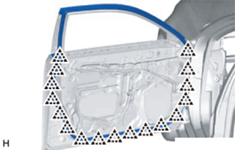
Detach the 17 clips and remove the front door weatherstrip.
-
-
REMOVE FRONT DOOR REAR BELT MOULDING END COVER LH
Tech Tips
When removing the front door rear belt moulding end cover, heat the front door panel and front door rear belt moulding end cover using a heat light.
Standard Item Temperature Front Door Panel 40 to 60°C (104 to 140°F) Front Door Rear Belt Moulding End Cover 20 to 30°C (68 to 86°F) Note
Do not heat the front door panel or front door rear belt moulding end cover excessively.
-
Text in Illustration *1 Protective Tape *2 Double-sided Tape Put protective tape around the front door rear belt moulding end cover.
-
Using a moulding remover, detach the 2 clips.
-
Detach the double-sided tape to remove the front door rear belt moulding end cover.
-
-
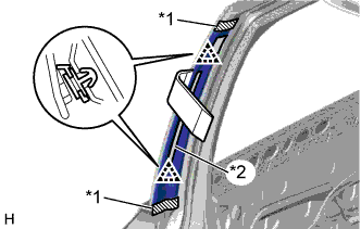
REMOVE FRONT DOOR REAR WINDOW FRAME MOULDING LH
Tech Tips
When removing the front door rear window frame moulding, heat the front door panel and front door rear window frame moulding using a heat light.
Standard Item Temperature Front Door Panel 40 to 60°C (104 to 140°F) Front Door Rear Window Frame Moulding 20 to 30°C (68 to 86°F) Note
Do not heat the front door panel or front door rear window frame moulding excessively.
-
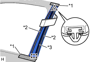
Text in Illustration *1 Protective Tape *2 Double-sided Tape *3 Butyl Tape Put protective tape around the front door rear window frame moulding.
-
Using a moulding remover, detach the clip.
-
Detach the double-sided tape and butyl tape, and then detach the guide and remove the front door rear window frame moulding.
-
-
REMOVE FRONT DOOR FRONT LOWER FRAME UPPER COVER LH
-
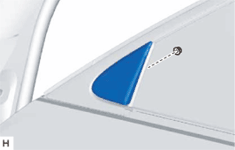
Remove the nut and front door front lower frame upper cover.
-
-
REMOVE FRONT DOOR OUTSIDE MOULDING SUB-ASSEMBLY LH
-
Put a 4 mm (0.157 in.) drill bit into a drill.
-
Wind tape around the drill bit approximately 5 mm (0.197 in.) from the tip of the drill as shown in the illustration.
Tech Tips
Tape the 4 mm (0.157 in.) drill bit to prevent the drill bit from going too deep.
-
Lightly press the drill against the 7 rivets and drill off the flanges of the 7 rivets.
CAUTION:
Be careful of the drilled rivet as it may become hot.
Note
-
Pressing the drill too firmly will cause the rivet to turn and result in the rivet not being drilled through.
-
Do not pry the rivet with the drill because this may cause damage to the installation holes of the rivet or the drill bit.
-
-
Detach the clip and claw and remove the front door outside moulding.
-
Using a vacuum cleaner, remove the rivet fragments and shavings from the drilled area.
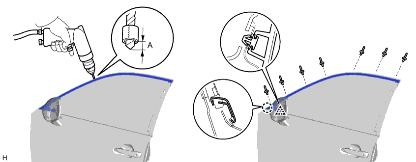
Standard Area Specified Condition A 5 mm (0.197 in.)
-
-
REMOVE FRONT DOOR NO. 3 WEATHERSTRIP LH
Tech Tips
In order to remove the front door No. 3 weatherstrip, first remove the front door panel.
-
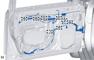
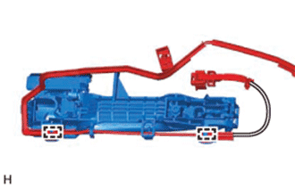
Detach the 8 clamps of the front door wire.
-
Remove the 2 bolts and disconnect the front door wire from the front door panel.
-
Remove the 4 bolts and front door panel.
CAUTION:
Be sure to perform this procedure with 2 or more persons as the part is very heavy.
-
Remove the 4 clips and front door No. 3 weatherstrip.
-