POWER TRUNK LID SYSTEM TERMINALS OF ECU

-
CHECK COWL SIDE JUNCTION BLOCK LH AND MAIN BODY ECU (MULTIPLEX NETWORK BODY ECU)
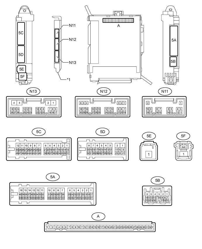
Text in Illustration *1 Main Body ECU (Multiplex Network Body ECU) - -
-
Remove the main body ECU (multiplex network body ECU) from the cowl side junction block LH Click here.
-
Connect the cowl side junction block LH connectors.
-
Measure the voltage and resistance according to the value(s) in the table below.
Terminal No. (Symbol) Wiring Color Terminal Description Condition Specified Condition A-11 (GND1) - Body ground None - Body ground Ground Always Below 1 Ω A-29 (ACC) - Body ground None - Body ground ACC power supply Power switch on (ACC) 11 to 14 V Power switch off Below 1 V A-30 (BECU) - Body ground None - Body ground Battery power supply Always 11 to 14 V A-31 (ALTB) - Body ground None - Body ground Battery power supply Always 11 to 14 V A-32 (IG) - Body ground None - Body ground Auxiliary battery power supply Power switch on (IG) 11 to 14 V Power switch off Below 1 V -
Install the main body ECU (multiplex network body ECU) to the cowl side junction block LH Click here.
-
Measure the voltage according to the value(s) in the table below.
Terminal No. (Symbol) Wiring Color Terminal Description Condition Specified Condition N13-5 (TMSW) - Body ground G - Body ground Luggage door opening cancel switch input signal Luggage door opening cancel switch is on Below 1 V Power switch off, all doors closed and luggage door opening cancel switch is off Pulse generation N13-8 (TSW) - Body ground Y - Body ground Luggage door opening switch input signal Luggage door opening switch is on Below 1 V Power switch off, all doors closed and luggage door opening switch is off Pulse generation N12-23 (TKUL) - Body ground GR - Body ground Luggage compartment door lock cylinder input signal Power switch off, luggage compartment door lock cylinder operated Below 1 V Power switch off, luggage compartment door lock cylinder not operated Pulse generation
-
-
CHECK LUGGAGE CLOSER MOTOR ASSEMBLY
-
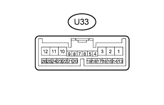
Disconnect the U33 luggage closer motor assembly connector.
-
Measure the resistance and voltage according to the value(s) in the table below.
Terminal No. (Symbol) Wiring Color Terminal Description Condition Specified Condition U33-8 (IG) - U33-11 (GND) B - W-B IG power supply Power switch on (IG) 11 to 14 V U33-10 (ECUB) - U33-11 (GND) P- W-B ECU power supply Always 11 to 14 V U33-11 (GND) - Body ground W-B - Body ground Ground Always Below 1 Ω U33-12 (B) - U33-11 (GND) B - W-B Battery power supply Always 11 to 14 V -
Reconnect the U33 motor connector.
-
Measure the voltage according to the value(s) in the table below.
Terminal No. (Symbol) Wiring Color Terminal Description Condition Specified Condition U33-1 (LCM-) - U33-11 (GND) G - W-B Luggage compartment door closer motor output signal Luggage compartment door closer is operated 11 to 14 V U33-2 (LCM+) - U33-11 (GND) B - W-B Luggage compartment door closer motor output signal Luggage compartment door closer is operated in reverse 11 to 14 V U33-4 (LDDN) - U33-11 (GND) BE - W-B Door control switch input signal Door control switch is on Below 1 V Power switch on (IG), luggage compartment door closed and door control switch is off Pulse generation U33-7 (HAF) - U33-11 (GND) GR - W-B Luggage compartment door closer half latch switch input signal Power switch on (IG), luggage compartment door open → fully closed Below 1 V → Pulse generation U33-20 (PAWL) - U33-11 (GND) GR - W-B Luggage compartment door closer pawl switch input signal Power switch on (IG), luggage compartment door open → fully closed Below 1 V → Pulse generation
-
-
CHECK CERTIFICATION ECU (SMART KEY ECU ASSEMBLY)
-
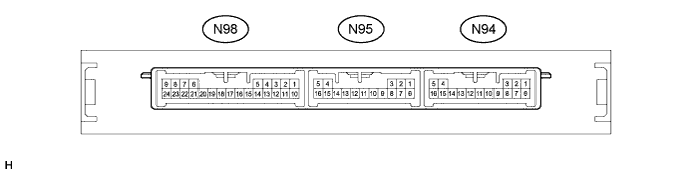
Disconnect the N94 and N95 certification ECU (smart key ECU assembly) connectors.
-
Measure the resistance and voltage according to the value(s) in the table below.
Terminal No. (Symbol) Wiring Color Terminal Description Condition Specified Condition N94-1 (E) - Body ground W-B - Body ground Ground Always Below 1 Ω N95-4 (CUTB) - Body ground P - Body ground Dark current cut fuse pin input signal* Always 11 to 14 V N95-5 (+B) - Body ground GR - Body ground Battery power supply Always 11 to 14 V N95-16 (IG) - Body ground B - Body ground Ignition power supply Power switch off Below 1 V Power switch on (IG) 11 to 14 V
-
*: In order to prevent the vehicle auxiliary battery from being depleted when the vehicle is shipped long distances, a fuse that cuts unnecessary electrical load while the vehicle is being shipped is set in the circuit. If the fuse is removed, the circuit becomes open. If the fuse that is between the vehicle auxiliary battery and terminal CUTB is removed and the circuit is open, the certification ECU (smart key ECU assembly) changes to a certain control mode (example: the transmission of electric waves every 0.25 seconds. that form the detection area stops).
-
-
Reconnect the N94 and N95 certification ECU (smart key ECU assembly) connectors.
-
Measure the voltage according to the value(s) in the table below.
Terminal No. (Symbol) Wiring Color Terminal Description Condition Specified Condition N98-22 (TSW5) - N94-1 (E) SB - W-B Luggage electrical key switch input signal Power switch on (IG), luggage compartment door is fully closed and luggage electrical key switch off Pulse generation
-