WINDSHIELD GLASS INSTALLATION

Tech Tips
-
Use the same procedure for RHD and LHD vehicles.
-
The procedure listed below is for LHD vehicles.
-
A bolt without a torque specification is shown in the standard bolt chart Click here.
-
CLEAN WINDSHIELD GLASS
-
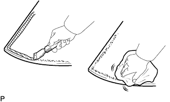
Using a scraper, remove the damaged stoppers, dam and adhesive sticking to the windshield glass.
-
Clean the outer circumference of the glass with non-residue solvent.
Note
-
Do not touch the glass surface after cleaning it.
-
Be careful not to damage the glass.
-
Even if using new glass, clean the glass with non-residue solvent.
-
-
-
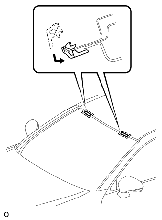
INSTALL NO. 1 WINDSHIELD GLASS STOPPER
-
Install 2 new No. 1windshield glass stoppers to the vehicle body as shown in the illustration.
Tech Tips
Only 2-piece type windshield glass stoppers are provided as supply parts. Use 2-piece type stoppers as replacements even if 1-piece type stoppers were originally installed.
-
-
INSTALL NO. 2 WINDSHIELD GLASS STOPPER
-
Apply Primer G to the glass where the stopper will be installed.
Note
-
Allow the primer to dry for 3 minutes or more.
-
Throw away any leftover primer.
-
Do not apply too much primer.
-
-
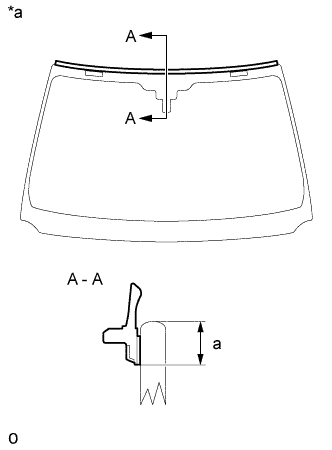
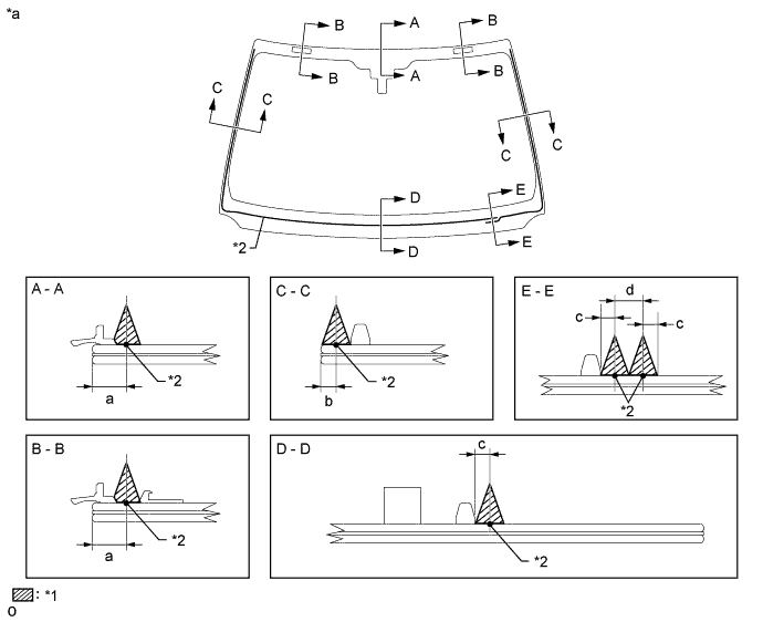
Install 2 new No. 2 windshield glass stoppers onto the glass as shown in the illustration.
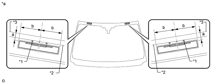
Text in Illustration *1 Ceramic Notch *2 Ceramic Line *3 Windshield Glass - - *a Backside - - Standard Area Specified Condition a 14.2 mm (0.560 in.) b 40.0 mm (1.57 in.) Tech Tips
Only 2-piece type windshield glass stoppers are provided as supply parts. Use the 2-piece type stoppers as replacements even if 1-piece type stoppers were originally installed.
-
-
INSTALL WINDSHIELD GLASS RETAINER
-
Apply Primer G to the glass where the retainer will be installed.
Note
-
Allow the primer to dry for 3 minutes or more.
-
Throw away any leftover primer.
-
Do not apply too much primer.
-
-
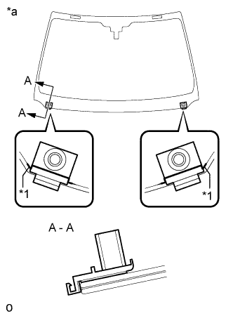
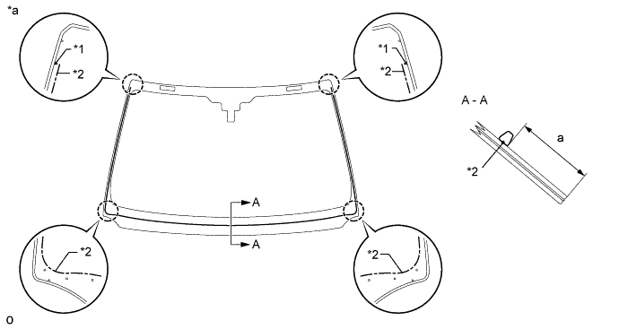
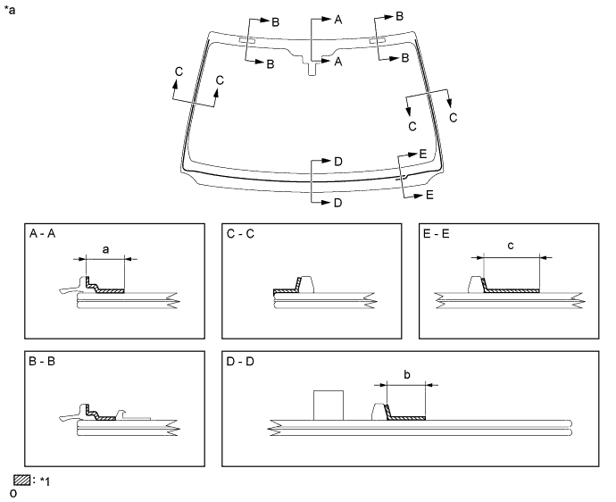
Text in Illustration *1 Ceramic Notch *a Back Side Install 2 new windshield glass retainers onto the glass as shown in the illustration.
-
-
INSTALL WINDSHIELD OUTSIDE MOULDING
-
Using a brush or sponge, coat the contact surface of the glass and moulding with Primer G.
Note
-
Allow the primer coating to dry for 3 minutes or more.
-
Do not coat the adhesive with Primer G.
-
Throw away any leftover primer.
-
-
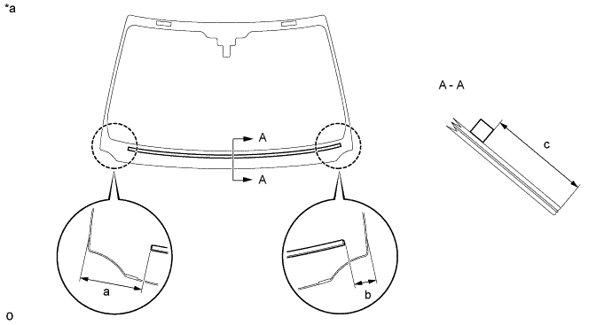
Text in Illustration *a Back Side Install the windshield outside moulding onto the windshield glass as shown in the illustration.
Standard Area Specified Condition a 7.2 mm (0.283 in.)
-
-
INSTALL WINDSHIELD GLASS ADHESIVE DAM
-
Apply Primer G to the glass where the glass adhesive dams will be installed.
Note
-
Allow the primer to dry for 3 minutes or more.
-
Throw away any leftover primer.
-
Do not apply too much primer.
-
-
Remove the peeling paper from the adhesive part of the dam. Install the dam (adhesive side) to the glass (Primer G area), but exclude the area above the notches on the upper part of the glass.
Text in Illustration *1 Ceramic Notch *2 Dam Center Line *a Back Side - - Standard Area Specified Condition a 61.0 mm (2.40 in.)
-
-
INSTALL WINDSHIELD GLASS SEAL
-
Apply Primer G to the glass where the windshield glass seal will be installed.
Note
-
Allow the primer to dry for 3 minutes or more.
-
Throw away any leftover primer.
-
Do not apply too much primer.
-
-
Remove the peeling paper from the windshield glass seal. Install the windshield glass seal to the glass.
Text in Illustration *a Back Side - - Standard Area Specified Condition a 80.3 mm (3.16 in.) b 29.5 mm (1.16 in.) c 75.0 mm (2.95 in.)
-
-
INSTALL WINDSHIELD GLASS
-
Position the glass.
-
Using suction cups, place the glass in the correct position.
-
Check that the entire contact surface of the glass rim is perfectly even.
-
Place matchmarks on the glass and vehicle body on the locations indicated in the illustration.
Note
Check that the stoppers are attached to the vehicle body correctly.
Tech Tips
-
Placing matchmarks is only necessary when installing new glass. If it is the reused glass, matchmarks should already be present.
-
When reusing the glass, check and correct the matchmark positions.
-
-
Using suction cups, remove the windshield glass.
-
-
Using a brush, apply Primer M to the exposed part of the vehicle body.
Note
-
Allow the primer to dry for 3 minutes or more.
-
Do not apply primer to the adhesive.
-
Throw away any leftover primer.
-
Do not apply too much primer.
-
-
Using a brush or sponge, apply Primer G to the contact surface of the windshield glass.
Text in Illustration *1 Primer G - - *a Back Side - - Standard Area Specified Condition a 13.0 mm (0.512 in.) b 11.0 mm (0.433 in.) c 19.0 mm (0.748 in.) Note
-
Allow the primer to dry for 3 minutes or more.
-
Throw away any leftover primer.
-
Do not apply too much primer.
Tech Tips
If the primer is applied to an area that is not specified, apply non-residue solvent to a clean cloth and wipe off the excess primer before it dries.
-
-
Apply adhesive to the windshield glass.
Adhesive Toyota Genuine Windshield Glass Adhesive or equivalent
-
Cut off the tip of the cartridge nozzle as shown in the illustration.
Tech Tips
After cutting off the tip, use all adhesive within the time written in the table below.
Usage Time Frame Temperature Usage Time Frame 35°C (95°F) 15 minutes 20°C (68°F) 1 hour 40 minutes 5°C (41°F) 8 hours -
Load the sealer gun with the cartridge.
-
Apply adhesive to the glass as shown in the illustration.
Text in Illustration *1 Adhesive *2 Adhesive Center Line *a Back Side - - Standard Area Specified Condition a 9.5 mm (0.374 in.) b 3.0 mm (0.118 in.) c 4.0 mm (0.157 in.) d 8.0 mm (0.315 in.)
-
-
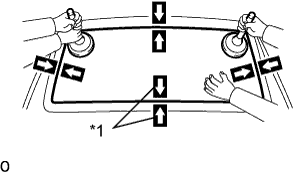
Text in Illustration *1 Matchmark Install the windshield glass to the vehicle body.
-
Using suction cups, position the windshield glass so that the matchmarks are aligned. Press it in gently along the rim.
-
Lightly press the outer surface of the windshield glass to ensure that it is securely fit to the vehicle body.
Note
-
Check that the stoppers are attached to the vehicle body correctly.
-
Check that the vehicle body and glass have a small gap between them.
-
-
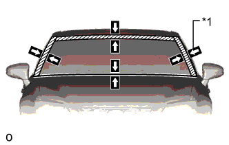
Hold the windshield glass in place securely with protective tape or equivalent until the adhesive hardens.
Note
Do not drive the vehicle for the amount of time written in the table below.
Minimum Time Temperature Minimum Time Prior to Driving Vehicle 35°C (95°F) 1 hour 30 minutes 20°C (68°F) 5 hours 5°C (41°F) 24 hours
-
-
-
CHECK FOR LEAK AND REPAIR
-
Conduct a leak test after the adhesive has completely hardened.
-
Seal any leaks with auto glass sealer.
-
-
INSTALL AIR CONDITIONING THERMISTOR ASSEMBLY
-
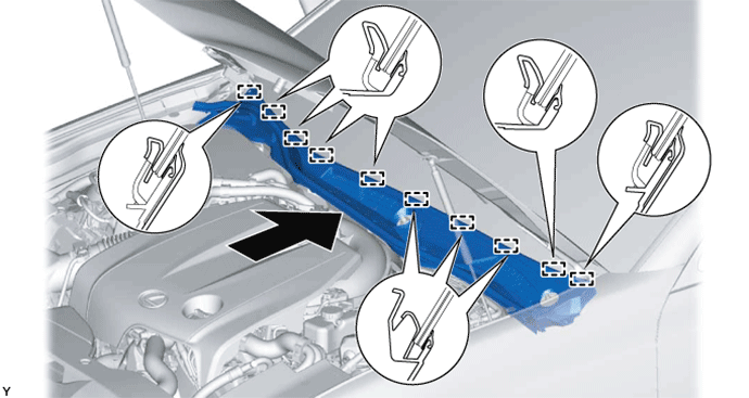
INSTALL ROOF HEADLINING ASSEMBLY
-
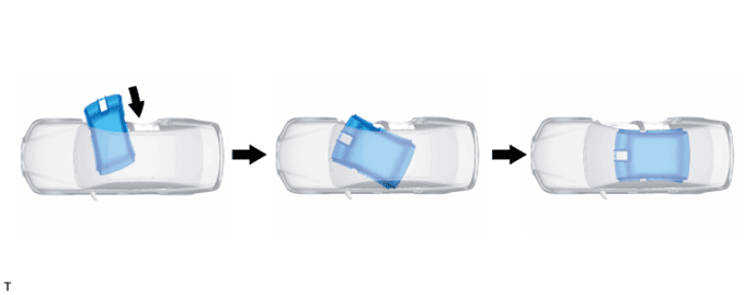
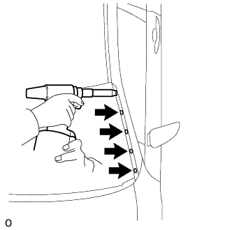
Insert the roof headlining through the front door and move it as shown in the illustration.
Note
-
Make sure that the roof headlining does not get caught on anything as it may become bent or damaged.
-
Do not damage the roof headlining or vehicle interior.
-
-
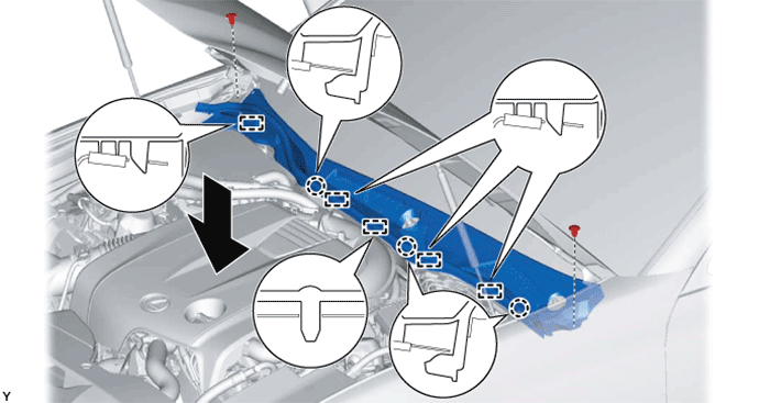
w/ Sliding Roof:
-
Attach the 12 claws, 3 clips, 3 guides and 11 fasteners to install the roof headlining.
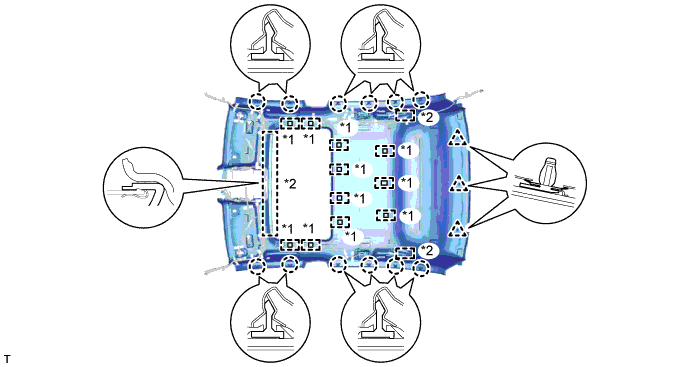
Text in Illustration *1 Fastener *2 Guide
-
-
w/o Sliding Roof:
-
Attach the 12 claws, 3 clips, 2 guides and 3 fasteners to install the roof headlining.
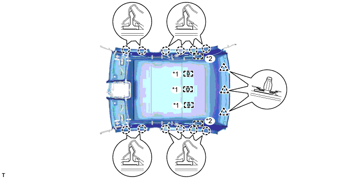
Text in Illustration *1 Fastener *2 Guide
-
-
Connect the connector and attach the clamp to the rear pillar RH.
-
Connect the connector and attach the 3 clamps to the front pillar RH.
-
Connect the connector and attach the 3 clamps to the rear pillar LH.
-
w/ Sliding Roof:
-
Connect the drive gear connector.
-
-
Connect the connectors for the rain sensor, inner mirror, air conditioning thermistor, lane recognition camera sensor and night view camera.
Note
After installing the roof headlining assembly, make sure that the lip of the front door opening trim weatherstrip LH and RH and the rear door opening trim weatherstrip LH and RH is not pinched.
-
-
INSTALL ASSIST GRIP SUB-ASSEMBLY
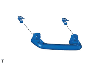
Tech Tips
Use the same procedure for both assist grips.
-
Attach the clips to the assist grip as shown in the illustration.
-
Attach the 2 clips to temporarily install the assist grip.
-
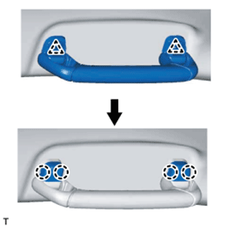
Attach the 4 claws to install the 2 new assist grip covers and fix the assist grip in place.
-
-
INSTALL VISOR HOLDER
Tech Tips
Use the same procedure for both visor holders.
-
Attach the 2 claws.
-
Push in the visor holder to install it.
-
-
INSTALL VISOR ASSEMBLY LH
-
Install the visor assembly LH with the 2 screws.
-
Attach the guide.
-
-
INSTALL VISOR ASSEMBLY RH
Tech Tips
Use the same procedure described for the LH side.
-
INSTALL VISOR BRACKET COVER
Tech Tips
Use the same procedure for both visor bracket covers.
-
Attach the 4 claws to install the visor bracket cover.
-
-
INSTALL RAIN SENSOR (w/ Rain Sensor)
-
INSTALL INNER REAR VIEW MIRROR ASSEMBLY
-
INSTALL MAP LIGHT ASSEMBLY
-
Connect the 2 connectors.
-
Attach the 4 clips and 2 guides to install the map light assembly.
-
-
INSTALL FRONT ROOF TOP GARNISH
-
w/ Night View System:
-
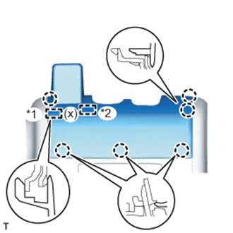
While being careful not to apply force to the camera, attach the 6 claws, guide and fastener to install the front roof top garnish.
Text in Illustration *1 Guide *2 Fastener Note
When removing and installing the front roof top garnish, do not apply force to the camera sensor located at (x).
-
-
w/o Night View System:
-
While being careful not to apply force to the camera (for vehicles with the lane keeping assist system), attach the 6 claws and guide to install the front roof top garnish.
Note
w/ Lane Keeping Assist System:
When removing and installing the front roof top garnish, do not apply force to the camera sensor located at (x).
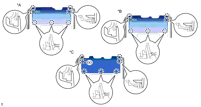
Text in Illustration *A for Standard *B w/ Rain Sensor *C w/ Lane Keeping Assist System - -
-
-
-
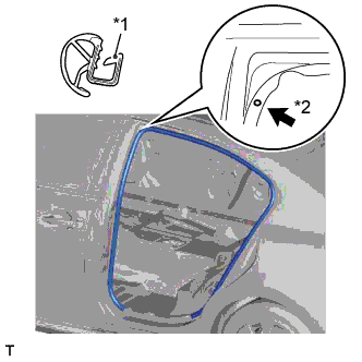
INSTALL FRONT PILLAR GARNISH LH
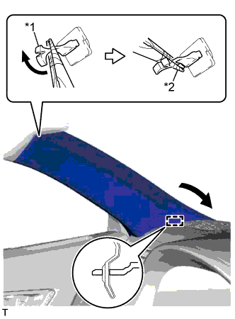
Text in Illustration *1 Front Pillar Garnish Clip *2 Protective Tape
-
Attach the guide.
-
Turn the end of the front pillar garnish clip 90° with needle-nose pliers and install it to the front pillar garnish LH.
Tech Tips
Tape the tips of the needle-nose pliers before use.
-
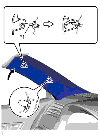
Text in Illustration *1 Front Pillar Garnish Clip Attach the 2 clips to install the front pillar garnish LH.
Note
After installing the front pillar garnish LH, make sure that the lip of the front door opening trim weatherstrip LH is not pinched.
-
-
INSTALL FRONT PILLAR GARNISH RH
Tech Tips
Use the same procedure described for the LH side.
-
INSTALL FRONT DOOR OPENING TRIM WEATHERSTRIP LH
Text in Illustration *1 Paint Mark *2 Mark Position
-
Align the paint mark on the rear door opening trim with the mark position on the vehicle and install the rear door opening trim weatherstrip as shown in the illustration.
-
-
INSTALL FRONT DOOR OPENING TRIM WEATHERSTRIP RH
Tech Tips
Use the same procedure described for the LH side.
-
INSTALL FRONT DOOR SCUFF PLATE LH
-
Attach the 10 claws and 4 clips to install the front door scuff plate LH.
-
-
INSTALL FRONT DOOR SCUFF PLATE RH
Tech Tips
Use the same procedure described for the LH side.
-
INSTALL COWL TOP VENTILATOR LOUVER SUB-ASSEMBLY
-
Engage the 10 guides as shown in the illustration.
-
Engage the 3 claws and 5 guides to install the cowl top ventilator louver sub-assembly as shown in the illustration.
-
Install the 2 clips.
-
Engage the claw, and install the outside windshield moulding to the cowl top ventilator louver sub-assembly.
-
-
INSTALL ENGINE ROOM SIDE COVER LH
-
Engage the guide.
-
Install the engine room side cover LH with the 2 clips.
-
-
CONNECT CABLE TO AUXILIARY BATTERY NEGATIVE TERMINAL
Note
When disconnecting the cable, some systems need to be initialized after the cable is reconnected Click here.
-
INSTALL LUGGAGE COMPARTMENT TRIM COVER LH
-
Install the luggage compartment trim cover.
-
-
REMOVE LUGGAGE COMPARTMENT FLOOR MAT
-
Install the luggage compartment floor mat.
-
-
INSTALL FRONT WIPER ARM AND BLADE ASSEMBLY RH
-
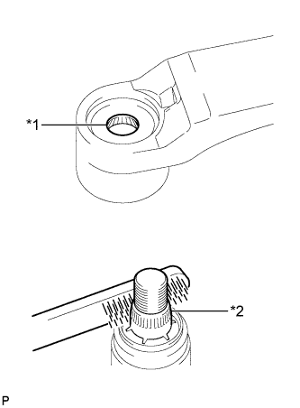
Text in Illustration *1 Wiper Arm Serration *2 Wiper Pivot Serration When reusing the front wiper arm and blade assembly RH:
-
Clean the wiper arm serrations.
-
-
When reusing the windshield wiper link assembly:
-
Clean the wiper pivot serrations with a wire brush.
-
-
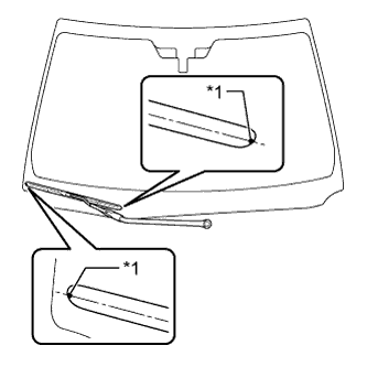
Text in Illustration *1 Ceramic Dot Install the front wiper arm and blade assembly RH with the nut to the position shown in the illustration.
- Torque:
- 22 N*m { 224 kgf*cm, 16 ft.*lbf }
Tech Tips
Hold the wiper arm by hand while tightening the nut.
-
Turn the power switch on (IG).
-
Operate the front wiper while spraying washer fluid onto the windshield glass. Make sure that the front wiper functions properly and the wiper does not come into contact with the vehicle body.
-
Lift each wiper arm twice after the wipers stop and check the wiper set position.
-
Turn the power switch off.
-
-
INSTALL FRONT WIPER ARM AND BLADE ASSEMBLY LH
-
Text in Illustration *1 Wiper Arm Serration *2 Wiper Pivot Serration When reusing the front wiper arm and blade assembly LH:
-
Clean the wiper arm serrations.
-
-
When reusing the windshield wiper link assembly:
-
Clean the wiper pivot serrations with a wire brush.
-
-
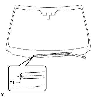
Text in Illustration *1 Ceramic Dot Install the front wiper arm and blade assembly LH with the nut to the position shown in the illustration.
- Torque:
- 22 N*m { 224 kgf*cm, 16 ft.*lbf }
Tech Tips
Hold the wiper arm by hand while tightening the nut.
-
-
INSTALL NO. 3 WINDSHIELD OUTSIDE MOULDING CLIP
-
Install a nose piece to an air riveter or hand riveter.
-
Insert the mandrel part of a new No. 3 windshield outside moulding clip into the nose piece.
-
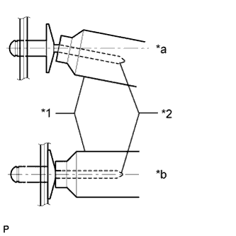
Text in Illustration *1 Riveter *2 Mandrel *a INCORRECT *b CORRECT 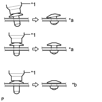
Text in Illustration *1 Riveter *a INCORRECT *b CORRECT 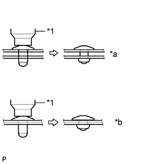
Text in Illustration *1 Riveter *a INCORRECT *b CORRECT Using the riveter, install the No. 3 windshield outside moulding clips shown in the illustration.
Tech Tips
If the clip cannot be cut, pull it once and cut it.
Note
-
Do not pry the clip with the riveter as this will cause damage to the riveter and mandrel.
Note
-
Confirm that the clips are seated properly against the moulding.
-
Do not tilt the riveter when installing the clip to the moulding.
-
Do not leave any space between the clip head and moulding.
Note
Do not leave any space between the moulding and body. Firmly hold together the 2 items while installing the clip.
-
-
-
INSTALL NO. 1 WINDSHIELD OUTSIDE MOULDING CLIP
-
Attach the 4 new No. 1 windshield outside moulding clips to install the windshield outside moulding LH.
-
-
INSTALL WINDSHIELD OUTSIDE MOULDING LH
-
Attach the 5 clips to the No. 1 windshield outside moulding clips.
-
Attach the claw and install the windshield moulding LH.
-
-
INSTALL WINDSHIELD OUTSIDE MOULDING RH
Tech Tips
Use the same procedure described for the LH side.
-
INSTALL CENTER ROOF DRIP SIDE FINISH MOULDING LH
-
Attach the 2 clips to install the center roof drip side finish moulding.
-
-
INSTALL CENTER ROOF DRIP SIDE FINISH MOULDING RH
Tech Tips
Use the same procedure described for the LH side.