POWER WINDOW CONTROL SYSTEM TERMINALS OF ECU

-
CHECK MULTIPLEX NETWORK MASTER SWITCH ASSEMBLY
-
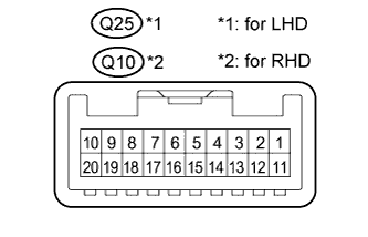
*1: for LHD
-
*2: for RHD
-
Disconnect the Q25*1 or Q10*2 multiplex network master switch connector.
-
Measure the voltage and resistance according to the value(s) in the table below.
for LHD Terminal No. (Symbol) Wiring Color Terminal Description Condition Specified Condition Q25-11 (B) - Q25-12 (GND) P - W-B Power source (IG) Always 11 to 14 V Q25-12 (GND) - Body ground W-B - Body ground Ground Always Below 1 Ω for RHD Terminal No. (Symbol) Wiring Color Terminal Description Condition Specified Condition Q10-11 (B) - Q10-12 (GND) P - W-B Power source (IG) Always 11 to 14 V Q10-12 (GND) - Body ground W-B - Body ground Ground Always Below 1 Ω If the result is not as specified, there may be a malfunction in the wire harness.
-
Reconnect the Q25*1 or Q10*2 multiplex network master switch connector.
-
Measure the voltage and waveform according to the value(s) in the table below.
for LHD Terminal No. (Symbol) Wiring Color Terminal Description Condition Specified Condition Q25-15 (DOWN) - Q25-12 (GND) R - W-B Power window motor down input Power switch on (IG), front power window switch LH not operated 11 to 14 V Q25-15 (DOWN) - Q25-12 (GND) R - W-B Power window motor down input Power switch on (IG), front power window switch LH down operated (Manual operation) Below 1 V Q25-18 (LED) - Q25-12 (GND) L - W-B LED illumination signal Power switch on (IG) 11 to 14 V Q25-18 (LED) - Q25-12 (GND) L - W-B LED illumination signal Power switch off Below 1 V Q25-20 (UP) - Q25-12 (GND) LG - W-B Power window motor up input Power switch on (IG), front power window switch LH not operated 11 to 14 V Q25-20 (UP) - Q25-12 (GND) LG - W-B Power window motor up input Power switch on (IG), front power window switch LH up operated (Manual operation) Below 1 V Q25-17 (LIN1) - Q25-12 (GND) Y - W-B LIN communication signal Power switch on (IG) Pulse generation for RHD Terminal No. (Symbol) Wiring Color Terminal Description Condition Specified Condition Q10-15 (DOWN) - Q10-12 (GND) R - W-B Power window motor down input Power switch on (IG), front power window switch RH not operated 11 to 14 V Q10-15 (DOWN) - Q10-12 (GND) R - W-B Power window motor down input Power switch on (IG), front power window switch RH down operated (Manual operation) Below 1 V Q10-18 (LED) - Q10-12 (GND) L - W-B LED illumination signal Power switch on (IG) 11 to 14 V Q10-18 (LED) - Q10-12 (GND) L - W-B LED illumination signal Power switch off Below 1 V Q10-20 (UP) - Q10-12 (GND) LG - W-B Power window motor up input Power switch on (IG), front power window switch RH not operated 11 to 14 V Q10-20 (UP) - Q10-12 (GND) LG - W-B Power window motor up input Power switch on (IG), front power window switch RH up operated (Manual operation) Below 1 V Q10-17 (LIN1) - Q10-12 (GND) Y - W-B LIN communication signal Power switch on (IG) Pulse generation
-
-
CHECK FRONT POWER WINDOW REGULATOR SWITCH ASSEMBLY
-
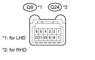
*1: for LHD
-
*2: for RHD
-
Disconnect the Q9*1 or Q24*2 front power window regulator switch assembly connector.
-
Measure the resistance according to the value(s) in the table below.
for LHD Terminal No. (Symbol) Wiring Color Terminal Description Condition Specified Condition Q9-5 (GND) - Body ground W-B - Body ground Ground Always Below 1 Ω for RHD Terminal No. (Symbol) Wiring Color Terminal Description Condition Specified Condition Q24-5 (GND) - Body ground W-B - Body ground Ground Always Below 1 Ω If the result is not as specified, there may be a malfunction in the wire harness.
-
Reconnect the Q9*1 or Q24*2 front power window regulator switch assembly connector.
-
Measure the voltage according to the value(s) in the table below.
for LHD Terminal No. (Symbol) Wiring Color Terminal Description Condition Specified Condition Q9-2 (UP) - Q9-5 (GND) LG - W-B Power window motor up input Power switch on (IG), front power window switch RH not operated 11 to 14 V Q9-2 (UP) - Q9-5 (GND) LG - W-B Power window motor up input Power switch on (IG), front power window switch RH up operated (Manual operation) Below 1 V Q9-4 (AUTO) - Q9-5 (GND) B - W-B Power window motor auto up or down input Power switch on (IG), front door glass RH fully open 11 to 14 V Q9-4 (AUTO) - Q9-5 (GND) B - W-B Power window motor auto up or down input Power switch on (IG), front power window RH auto up or down function operating Below 1 V Q9-4 (AUTO) - Q9-5 (GND) B - W-B Power window motor auto up or down input Power switch on (IG), front door glass RH fully closed 11 to 14 V Q9-8 (LED) - Q9-5 (GND) L - W-B LED illumination signal Power switch on (IG) 11 to 14 V Q9-8 (LED) - Q9-5 (GND) L - W-B LED illumination signal Power switch off Below 1 V Q9-10 (DOWN) - Q9-5 (GND) R - W-B Power window motor down input Power switch on (IG), front power window switch RH not operated 11 to 14 V Q9-10 (DOWN) - Q9-5 (GND) R - W-B Power window motor down input Power switch on (IG), front power window switch RH down operated (Manual operation) Below 1 V for RHD Terminal No. (Symbol) Wiring Color Terminal Description Condition Specified Condition Q24-2 (UP) - Q24-5 (GND) LG - W-B Power window motor up input Power switch on (IG), front power window switch LH not operated 11 to 14 V Q24-2 (UP) - Q24-5 (GND) LG - W-B Power window motor up input Power switch on (IG), front power window switch LH up operated (Manual operation) Below 1 V Q24-4 (AUTO) - Q24-5 (GND) P - W-B Power window motor auto up or down input Power switch on (IG), front door glass LH fully open 11 to 14 V Q24-4 (AUTO) - Q24-5 (GND) P - W-B Power window motor auto up or down input Power switch on (IG), front power window LH auto up or down function operating Below 1 V Q24-4 (AUTO) - Q24-5 (GND) P - W-B Power window motor auto up or down input Power switch on (IG), front door glass LH fully closed 11 to 14 V Q24-8 (LED) - Q24-5 (GND) L - W-B LED illumination signal Power switch on (IG) 11 to 14 V Q24-8 (LED) - Q24-5 (GND) L - W-B LED illumination signal Power switch off Below 1 V Q24-10 (DOWN) - Q24-5 (GND) R - W-B Power window motor down input Power switch on (IG), front power window switch LH not operated 11 to 14 V Q24-10 (DOWN) - Q24-5 (GND) R - W-B Power window motor down input Power switch on (IG), front power window switch LH down operated (Manual operation) Below 1 V
-
-
CHECK REAR POWER WINDOW REGULATOR SWITCH ASSEMBLY LH
-
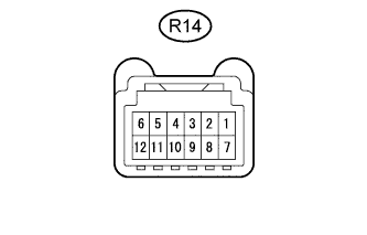
Disconnect the R14 rear power window regulator switch LH connector.
-
Measure the resistance according to the value(s) in the table below.
Terminal No. (Symbol) Wiring Color Terminal Description Condition Specified Condition R14-5 (GND) - Body ground W-B - Body ground Ground Always Below 1 Ω If the result is not as specified, there may be a malfunction in the wire harness.
-
Reconnect the R14 rear power window regulator switch LH connector.
-
Measure the voltage according to the value(s) in the table below.
Terminal No. (Symbol) Wiring Color Terminal Description Condition Specified Condition R14-2 (UP) - R14-5 (GND) W - W-B Power window motor up input Power switch on (IG), rear power window switch LH not operated 11 to 14 V R14-2 (UP) - R14-5 (GND) W - W-B Power window motor up input Power switch on (IG), rear power window switch LH down operated (Manual operation) Below 1 V R14-4 (AUTO) - R14-5 (GND) P - W-B Power window motor auto up or down input Power switch on (IG), rear door glass LH fully open 11 to 14 V R14-4 (AUTO) - R14-5 (GND) P - W-B Power window motor auto up or down input Power switch on (IG), rear power window LH auto up or down function operating Below 1 V R14-4 (AUTO) - R14-5 (GND) P - W-B Power window motor auto up or down input Power switch on (IG), rear door glass LH fully closed 11 to 14 V R14-8 (LED) - R14-5 (GND) L - W-B LED illumination signal Power switch on (IG) 11 to 14 V R14-8 (LED) - R14-5 (GND) L - W-B LED illumination signal Power switch off Below 1 V R14-10 (DOWN) - R14-5 (GND) R - W-B Power window motor down input Power switch on (IG), rear power window switch LH not operated 11 to 14 V R14-10 (DOWN) - R14-5 (GND) R - W-B Power window motor down input Power switch on (IG), rear power window switch LH down operated (Manual operation) Below 1 V
-
-
CHECK REAR POWER WINDOW REGULATOR SWITCH ASSEMBLY RH
-
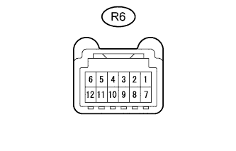
Disconnect the R6 rear power window regulator switch RH connector.
-
Measure the resistance according to the value(s) in the table below.
Terminal No. (Symbol) Wiring Color Terminal Description Condition Specified Condition R6-5 (GND) - Body ground W-B - Body ground Ground Always Below 1 Ω If the result is not as specified, there may be a malfunction in the wire harness.
-
Reconnect the R6 rear power window regulator switch RH connector.
-
Measure the voltage according to the value(s) in the table below.
Terminal No. (Symbol) Wiring Color Terminal Description Condition Specified Condition R6-2 (UP) - R6-5 (GND) W - W-B Power window motor up input Power switch on (IG), rear power window switch RH not operated 11 to 14 V R6-2 (UP) - R6-5 (GND) W - W-B Power window motor up input Power switch on (IG), rear power window switch RH down operated (Manual operation) Below 1 V R6-4 (AUTO) - R6-5 (GND) P - W-B Power window motor auto up or down input Power switch on (IG), rear door glass RH fully open 11 to 14 V R6-4 (AUTO) - R6-5 (GND) P - W-B Power window motor auto up or down input Power switch on (IG), rear power window RH auto up or down function operating Below 1 V R6-4 (AUTO) - R6-5 (GND) P - W-B Power window motor auto up or down input Power switch on (IG), rear door glass RH fully closed 11 to 14 V R6-8 (LED) - R6-5 (GND) L - W-B LED illumination signal Power switch on (IG) 11 to 14 V R6-8 (LED) - R6-5 (GND) L - W-B LED illumination signal Power switch off Below 1 V R6-10 (DOWN) - R6-5 (GND) R - W-B Power window motor down input Power switch on (IG), rear power window switch RH not operated 11 to 14 V R6-10 (DOWN) - R6-5 (GND) R - W-B Power window motor down input Power switch on (IG), rear power window switch RH down operated (Manual operation) Below 1 V
-
-
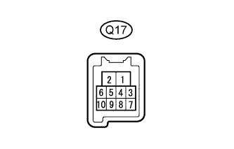
CHECK FRONT POWER WINDOW REGULATOR MOTOR ASSEMBLY LH
-
Disconnect the Q17 front power window regulator motor LH connector.
-
Measure the voltage and resistance according to the value(s) in the table below.
Terminal No. (Symbol) Wiring Color Terminal Description Condition Specified Condition Q17-1 (E) - Body ground BR - Body ground Ground Always Below 1 Ω Q17-2 (B) - Q17-1 (E) R - BR Power source Always 11 to 14 V If the result is not as specified, there may be a malfunction in the wire harness.
-
Reconnect the Q17 front power window regulator motor LH connector.
-
Measure the voltage and waveform according to the value(s) in the table below.
Terminal No. (Symbol) Wiring Color Terminal Description Condition Specified Condition Q17-5 (LED) - Q17-1 (E) L - BR LED illumination signal Power switch on (IG) 11 to 14 V Q17-5 (LED) - Q17-1 (E) L - BR LED illumination signal Power switch off Below 1 V Q17-7 (DWN1) - Q17-1 (E) R - BR Power window motor down output Power switch on (IG), front power window switch LH not operated 11 to 14 V Q17-7 (DWN1) - Q17-1 (E) R - BR Power window motor down output Power switch on (IG), front power window switch LH down operated (Manual operation) Below 1 V Q17-7 (DWN1) - Q17-1 (E) R - BR Power window motor down output Power switch on (IG), front door glass LH fully closed 11 to 14 V Q17-7 (DWN1) - Q17-1 (E) R - BR Power window motor down output Power switch on (IG), front power window switch LH down operated (Automatic operation) Below 1 V Q17-7 (DWN1) - Q17-1 (E) R - BR Power window motor down output Power switch on (IG), front door glass LH fully open 11 to 14 V Q17-10 (UP1) - Q17-1 (E) LG - BR Power window motor up output Power switch on (IG), front power window switch LH not operated 11 to 14 V Q17-10 (UP1) - Q17-1 (E) LG - BR Power window motor up output Power switch on (IG), front power window switch LH up operated (Manual operation) Below 1 V Q17-10 (UP1) - Q17-1 (E) LG - BR Power window motor up output Power switch on (IG), front door glass LH fully open 11 to 14 V Q17-10 (UP1) - Q17-1 (E) LG - BR Power window motor up output Power switch on (IG), front power window switch LH down operated (Automatic operation) Below 1 V Q17-10 (UP1) - Q17-1 (E) LG - BR Power window motor up output Power switch on (IG), front door glass LH fully closed 11 to 14 V Q17-9 (LIN) - Q17-1 (E) GR - BR LIN communication signal Power switch on (IG) Pulse generation
-
-
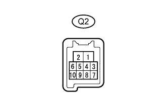
CHECK FRONT POWER WINDOW REGULATOR MOTOR ASSEMBLY RH
-
Disconnect the Q2 front power window regulator motor RH connector.
-
Measure the voltage and resistance according to the value(s) in the table below.
Terminal No. (Symbol) Wiring Color Terminal Description Condition Specified Condition Q2-1 (E) - Body ground BR - Body ground Ground Always Below 1 Ω Q2-2 (B) - Q2-1 (E) R - BR Power source Always 11 to 14 V If the result is not as specified, there may be a malfunction in the wire harness.
-
Reconnect the Q2 front power window regulator motor RH connector.
-
Measure the voltage and waveform according to the value(s) in the table below.
Terminal No. (Symbol) Wiring Color Terminal Description Condition Specified Condition Q2-5 (LED) - Q2-1 (E) L - BR LED illumination signal Power switch on (IG) 11 to 14 V Q2-5 (LED) - Q2-1 (E) L - BR LED illumination signal Power switch off Below 1 V Q2-7 (DWN1) - Q2-1 (E) R - BR Power window motor down output Power switch on (IG), front power window switch RH not operated 11 to 14 V Q2-7 (DWN1) - Q2-1 (E) R - BR Power window motor down output Power switch on (IG), front power window switch RH down operated (Manual operation) Below 1 V Q2-7 (DWN1) - Q2-1 (E) R - BR Power window motor down output Power switch on (IG), front door glass RH fully closed 11 to 14 V Q2-7 (DWN1) - Q2-1 (E) R - BR Power window motor down output Power switch on (IG), front power window switch RH down operated (Automatic operation) Below 1 V Q2-7 (DWN1) - Q2-1 (E) R - BR Power window motor down output Power switch on (IG), front door glass RH fully open 11 to 14 V Q2-10 (UP1) - Q2-1 (E) LG - BR Power window motor up output Power switch on (IG), front power window switch RH not operated 11 to 14 V Q2-10 (UP1) - Q2-1 (E) LG - BR Power window motor up output Power switch on (IG), front power window switch RH up operated (Manual operation) Below 1 V Q2-10 (UP1) - Q2-1 (E) LG - BR Power window motor up output Power switch on (IG), front door glass RH fully open 11 to 14 V Q2-10 (UP1) - Q2-1 (E) LG - BR Power window motor up output Power switch on (IG), front power window switch RH down operated (Automatic operation) Below 1 V Q2-10 (UP1) - Q2-1 (E) LG - BR Power window motor up output Power switch on (IG), front door glass RH fully closed 11 to 14 V Q2-9 (LIN) - Q2-1 (E) V - BR LIN communication signal Power switch on (IG) Pulse generation
-
-
CHECK REAR POWER WINDOW REGULATOR MOTOR ASSEMBLY LH

-
Disconnect the R9 rear power window regulator motor LH connector.
-
Measure the voltage and resistance according to the value(s) in the table below.
Terminal No. (Symbol) Wiring Color Terminal Description Condition Specified Condition R9-1 (E) - Body ground W-B - Body ground Ground Always Below 1 Ω R9-2 (B) - R9-1 (E) R - W-B Power source Always 11 to 14 V If the result is not as specified, there may be a malfunction in the wire harness.
-
Reconnect the R9 rear power window regulator motor LH connector.
-
Measure the voltage and waveform according to the value(s) in the table below.
Terminal No. (Symbol) Wiring Color Terminal Description Condition Specified Condition R9-5 (LED) - R9-1 (E) L - W-B LED illumination signal Power switch on (IG) 11 to 14 V R9-5 (LED) - R9-1 (E) L - W-B LED illumination signal Power switch off Below 1 V R9-7 (DWN1) - R9-1 (E) R - W-B Power window motor down input Power switch on (IG), rear power window switch LH not operated 11 to 14 V R9-7 (DWN1) - R9-1 (E) R - W-B Power window motor down input Power switch on (IG), rear power window switch LH down operated (Manual operation) Below 1 V R9-7 (DWN1) - R9-1 (E) R - W-B Power window motor down input Power switch on (IG), rear door glass LH fully closed 11 to 14 V R9-7 (DWN1) - R9-1 (E) R - W-B Power window motor down input Power switch on (IG), rear power window switch LH down operated (Automatic operation) Below 1 V R9-7 (DWN1) - R9-1 (E) R - W-B Power window motor down input Power switch on (IG), rear door glass LH fully open 11 to 14 V R9-10 (UP1) - R9-1 (E) W - W-B Power window motor up output Power switch on (IG), rear power window switch LH not operated 11 to 14 V R9-10 (UP1) - R9-1 (E) W - W-B Power window motor up output Power switch on (IG), rear power window switch LH up operated (Manual operation) Below 1 V R9-10 (UP1) - R9-1 (E) W - W-B Power window motor up output Power switch on (IG), rear door glass LH fully open 11 to 14 V R9-10 (UP1) - R9-1 (E) W - W-B Power window motor up output Power switch on (IG), rear power window switch LH down operated (Automatic operation) Below 1 V R9-10 (UP1) - R9-1 (E) W - W-B Power window motor up output Power switch on (IG), rear door glass LH fully closed 11 to 14 V R9-9 (LIN) - R9-1 (E) L - W-B LIN communication signal Power switch on (IG) Pulse generation
-
-
CHECK REAR POWER WINDOW REGULATOR MOTOR ASSEMBLY RH

-
Disconnect the R1 rear power window regulator motor RH connector.
-
Measure the voltage and resistance according to the value(s) in the table below.
Terminal No. (Symbol) Wiring Color Terminal Description Condition Specified Condition R1-1 (E) - Body ground W-B - Body ground Ground Always Below 1 Ω R1-2 (B) - R1-1 (E) R - W-B Power source Always 11 to 14 V If the result is not as specified, there may be a malfunction in the wire harness.
-
Reconnect the R1 rear power window regulator motor RH connector.
-
Measure the voltage and waveform according to the value(s) in the table below.
Terminal No. (Symbol) Wiring Color Terminal Description Condition Specified Condition R1-5 (LED) - R1-1 (E) L - W-B LED illumination signal Power switch on (IG) 11 to 14 V R1-5 (LED) - R1-1 (E) L - W-B LED illumination signal Power switch off Below 1 V R1-7 (DWN1) - R1-1 (E) R - W-B Power window motor down output Power switch on (IG), rear power window switch RH not operated 11 to 14 V R1-7 (DWN1) - R1-1 (E) R - W-B Power window motor down output Power switch on (IG), rear power window switch RH down operated (Manual operation) Below 1 V R1-7 (DWN1) - R1-1 (E) R - W-B Power window motor down output Power switch on (IG), rear door glass RH fully closed 11 to 14 V R1-7 (DWN1) - R1-1 (E) R - W-B Power window motor down output Power switch on (IG), rear power window switch RH down operated (Automatic operation) Below 1 V R1-7 (DWN1) - R1-1 (E) R - W-B Power window motor down output Power switch on (IG), rear door glass RH fully open 11 to 14 V R1-10 (UP1) - R1-1 (E) W - W-B Power window motor up output Power switch on (IG), rear power window switch RH not operated 11 to 14 V R1-10 (UP1) - R1-1 (E) W - W-B Power window motor up output Power switch on (IG), rear power window switch RH up operated (Manual operation) Below 1 V R1-10 (UP1) - R1-1 (E) W - W-B Power window motor up output Power switch on (IG), rear door glass RH fully open 11 to 14 V R1-10 (UP1) - R1-1 (E) W - W-B Power window motor up output Power switch on (IG), rear power window switch RH up operated (Automatic operation) Below 1 V R1-10 (UP1) - R1-1 (E) W - W-B Power window motor up output Power switch on (IG), rear door glass RH fully closed 11 to 14 V R1-9 (LIN) - R1-1(E) L - W-B LIN communication signal Power switch on (IG) Pulse generation
-
-
CHECK COWL SIDE JUNCTION BLOCK LH, MAIN BODY ECU (MULTIPLEX NETWORK BODY ECU)
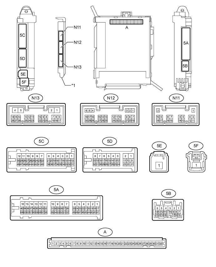
Text in Illustration *1 Main Body ECU (Multiplex Network Body ECU) - -
-
Remove the main body ECU (multiplex network body ECU) Click here.
-
Connect the cowl side junction block LH connectors.
-
Measure the voltage and resistance according to the value(s) in the table below.
Terminal No. (Symbol) Wiring Color Terminal Description Condition Specified Condition A-30 (BECU) - Body ground - Power source Always 11 to 14 V A-31 (ALTB) - Body ground - Power source Always 11 to 14 V A-32 (IG) - Body ground - Power source (IG) Power switch on (IG) 11 to 14 V A-32 (IG) - Body ground - Power source (IG) Power switch off Below 1 V A-29 (ACC) - Body ground - Power source (ACC) Power switch on (ACC) 11 to 14 V A-29 (ACC) - Body ground - Power source (ACC) Power switch off Below 1 V A-11 (GND1) - Body ground - Ground Always Below 1 Ω N13-3 (GND2) - Body ground W-B - Body ground Ground Always Below 1 Ω If the result is not as specified, there may be a malfunction in the wire harness or cowl side junction block LH.
-
Install the main body ECU (multiplex network body ECU) Click here.
-
Measure the voltage and waveform according to the value(s) in the table below.
Terminal No. (Symbol) Wiring Color Terminal Description Condition Specified Condition 5C-44 (FLCY) - Body ground R - Body ground Front door LH courtesy switch input Front door LH open Below 1 V 5C-44 (FLCY) - Body ground R - Body ground Front door LH courtesy switch input Front door LH closed Pulse generation 5A-33 (FRCY) - Body ground R - Body ground Front door RH courtesy switch input Front door RH open Below 1 V 5A-33 (FRCY) - Body ground R - Body ground Front door RH courtesy switch input Front door RH closed Pulse generation 5C-28 (LIN2) - Body ground Y - Body ground LIN communication signal Power switch on (IG) Pulse generation 5C-29 (LIN2) - Body ground Y - Body ground LIN communication signal Power switch on (IG) Pulse generation 5A-50 (LIN2) - Body ground Y - Body ground LIN communication signal Power switch on (IG) Pulse generation 5A-56 (LIN2) - Body ground Y - Body ground LIN communication signal Power switch on (IG) Pulse generation
-
-
CHECK FRONT MULTIPLEX NETWORK DOOR ECU LH
-
*: for LHD

-
Disconnect the Q19 front multiplex network door ECU LH connector.
-
Measure the voltage and resistance according to the value(s) in the table below.
Terminal No. (Symbol) Wiring Color Terminal Description Condition Specified Condition Q19-4 (CPUB) - Q19-1 (GND) P - W-B Power source Always 11 to 14 V Q19-6 (BDR) - Q19-1 (GND) V - W-B Power source Always 11 to 14 V Q19-16 (BCUT)* - Q19-1 (GND) W - W-B Power source Always 11 to 14 V Q19-3 (SIG) - Q19-1 (GND) B - W-B Power source (IG) Power switch on (IG) 11 to 14 V Q19-3 (SIG) - Q19-1 (GND) B - W-B Power source (IG) Power switch off Below 1 V Q19-1 (GND) - Body ground W-B - Body ground Ground Always Below 1 Ω If the result is not as specified, there may be a malfunction in the wire harness.
-
Reconnect the Q19 front multiplex network door ECU LH connector.
-
Measure the voltage, resistance and waveform according to the value(s) in the table below.
Terminal No. (Symbol) Wiring Color Terminal Description Condition Specified Condition Q19-5 (BDRJ) - Q19-1 (GND) R - W-B Power window regulator motor power supply Always 11 to 14 V Q19-2 (PWE) - Body ground BR - Body ground Ground Always Below 1 V Q19-15 (CPBJ)* - Q19-1 (GND) P - W-B Multiplex network master switch power supply Always 11 to 14 V Q19-9 (SGND) - Body ground W-B - Body ground Ground Always Below 1 Ω Q18-9 (LIN3) - Q19-1 (GND) GR - W-B LIN communication signal Power switch on (IG) Pulse generation Q18-8 (LIN2)* - Q19-1 (GND) Y - W-B LIN communication signal Power switch on (IG) Pulse generation Q18-18 (LIN1) - Q19-1 (GND) Y - W-B LIN communication signal Power switch on (IG) Pulse generation
-
-
CHECK FRONT MULTIPLEX NETWORK DOOR ECU RH
-
*: for RHD

-
Disconnect the Q4 front multiplex network door ECU RH connector.
-
Measure the voltage and resistance according to the value(s) in the table below.
Terminal No. (Symbol) Wiring Color Terminal Description Condition Specified Condition Q4-6 (BDR) - Body ground V - Body ground Power source Always 11 to 14 V Q4-4 (CPUB) - Body ground P - Body ground Power source Always 11 to 14 V Q4-16 (BCUT)* - Body ground L - Body ground Power source Always 11 to 14 V Q4-3 (SIG) - Q4-1 (GND) B - W-B Power source (IG) Power switch on (IG) 11 to 14 V Q4-3 (SIG) - Q4-1 (GND) B - W-B Power source (IG) Power switch off Below 1 V Q4-1 (GND) - Body ground W-B - Body ground Ground Always Below 1 Ω If the result is not as specified, there may be a malfunction in the wire harness.
-
Reconnect the Q4 front multiplex network door ECU RH connector.
-
Measure the voltage, resistance and waveform according to the value(s) in the table below.
Terminal No. (Symbol) Wiring Color Terminal Description Condition Specified Condition Q4-2 (PWE) - Body ground BR - Body ground Ground Always Below 1 V Q4-5 (BDRJ) - Body ground R - Body ground Power window regulator motor power supply Always 11 to 14 V Q4-15 (CPBJ)* - Body ground P - Body ground Multiplex network master switch power supply Always 11 to 14 V Q4-9 (SGND) - Body ground W-B - Body ground Ground Always Below 1 Ω Q3-9 (LIN3) - Q4-1 (GND) V - W-B LIN communication signal Power switch on (IG) Pulse generation Q3-8 (LIN2)* - Q4-1 (GND) Y - W-B LIN communication signal Power switch on (IG) Pulse generation Q3-18 (LIN1) - Q4-1 (GND) Y - W-B LIN communication signal Power switch on (IG) Pulse generation
-