INSTRUMENT PANEL SAFETY PAD REMOVAL

Tech Tips
-
Use the same procedure for RHD and LHD vehicles.
-
The procedure listed below is for LHD vehicles.
-
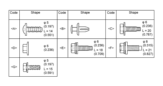
TABLE OF BOLT, SCREW AND NUT
Tech Tips
All bolts, screws, nuts and clips relevant to installing and removing the instrument panel are shown along with their alphabet code in the table below.
-
DISABLE AUTO TILT AWAY FUNCTION
-
Disable the autoaway/return function by changing the customize parameter Click here.
CAUTION:
Record the current customize parameter setting (whether the autoaway/return function is enabled or disabled) in order to restore the current setting after finishing the operation.
Tech Tips
Performing the above operation causes the autoaway/return function to be disabled when the power switch is turned off.
-
Turn the power switch on (IG). Operate the tilt and telescopic switch to fully extend and lower the steering column assembly.
-
Turn the power switch off.
-
-
REMOVE LUGGAGE COMPARTMENT FLOOR MAT
-
Remove the luggage compartment floor mat.
-
-
REMOVE LUGGAGE COMPARTMENT TRIM COVER LH
-
Remove the luggage compartment trim cover.
-
-
PRECAUTION
Note
After turning the power switch off, waiting time may be required before disconnecting the cable from the auxiliary battery terminal. Therefore, make sure to read the disconnecting the cable from the auxiliary battery terminal notice before proceeding with work Click here.
-
DISCONNECT CABLE FROM AUXILIARY BATTERY NEGATIVE TERMINAL
CAUTION:
Wait at least 90 seconds after disconnecting the cable from the negative (-) auxiliary battery terminal to disable the SRS system.
Note
When disconnecting the cable, some systems need to be initialized after the cable is reconnected Click here.
-
REMOVE CONSOLE BOX ASSEMBLY
-
REMOVE FRONT DOOR SCUFF PLATE LH
-
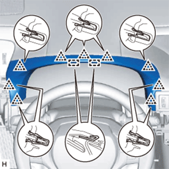
Place your hands on the inner portion of the front door scuff plate LH and detach the 2 claws labeled A, 6 claws labeled B and 2 claws labeled C in the order shown in the illustration.
-
Raise the front door scuff plate LH to detach the 4 clips on the outer side and remove it.
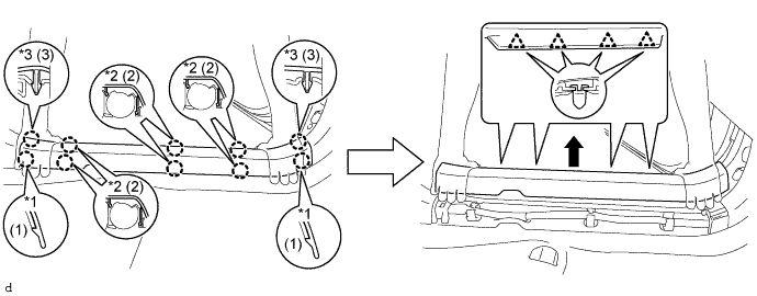
Text in Illustration *1 Claw A *2 Claw B *3 Claw C - -
-
-
REMOVE FRONT DOOR SCUFF PLATE RH
Tech Tips
Use the same procedure described for the LH side.
-
REMOVE FRONT DOOR OPENING TRIM COVER LH
-
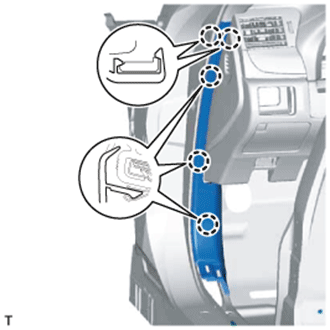
Detach the 5 claws and remove the front door opening trim cover LH.
-
-
REMOVE FRONT DOOR OPENING TRIM COVER RH
Tech Tips
Use the same procedure described for the LH side.
-
REMOVE FRONT PILLAR GARNISH LH
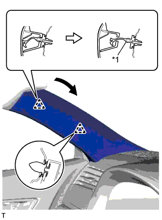
Text in Illustration *1 Front Pillar Garnish Clip
-
Pull the upper part of the garnish toward the inside of the cabin and detach the 2 clips.
Tech Tips
Make the front pillar garnish LH hang down from the front pillar garnish clip.
-
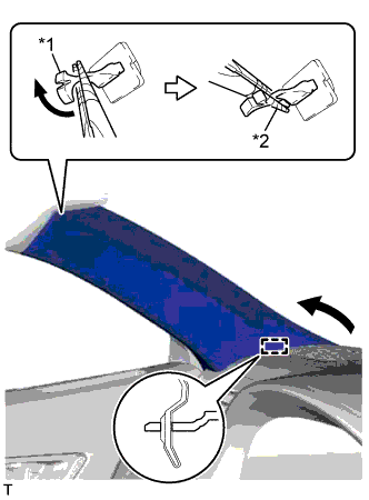
Text in Illustration *1 Front Pillar Garnish Clip *2 Protective Tape Turn the end of the front pillar garnish clip 90° with needle-nose pliers and remove it from the front pillar garnish LH.
Note
-
Front pillar garnish clips are reusable if they are not removed from the vehicle and have no damage.
-
Replace the front pillar garnish clips with new ones if they are removed from the vehicle.
Tech Tips
Tape the tips of the needle-nose pliers before use.
-
-
Detach the guide and remove the front pillar garnish LH.
-
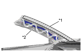
Text in Illustration *1 Adhesive Tape *2 Protective Cover Protect the curtain shield airbag assembly.
-
Completely cover the airbag with a cloth or nylon sheet and secure the ends of the cover with adhesive tape as shown in the illustration.
Note
Cover the curtain shield airbag with a protective cover as soon as the front pillar garnish is removed.
-
-
-
REMOVE FRONT PILLAR GARNISH RH
Tech Tips
Use the same procedure described for the LH side.
-
REMOVE INSTRUMENT SIDE PANEL LH
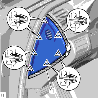
Text in Illustration *1 Protective Tape
-
Put protective tape around the instrument side panel LH.
-
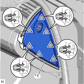
Using a moulding remover, detach the 7 clips and remove the instrument side panel LH.
-
-
REMOVE NO. 1 INSTRUMENT PANEL GARNISH SUB-ASSEMBLY
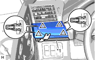
Text in Illustration *1 Protective Tape
-
Put protective tape around the No. 1 instrument panel garnish sub-assembly.
-
Using a moulding remover, detach the 4 clips and remove the No. 1 instrument panel garnish sub-assembly.
-
-
REMOVE NO. 1 INSTRUMENT PANEL UNDER COVER SUB-ASSEMBLY
-
Remove the 3 screws <A>.
-
Detach the 2 claws.
-
Disconnect the connectors, detach the clamp and remove the No. 1 instrument panel under cover sub-assembly.
-
-
REMOVE NO. 1 INSTRUMENT PANEL SAFETY PAD SUB-ASSEMBLY
-
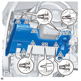
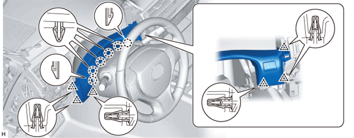
Detach the 9 clips and guide.
-
Disconnect the connectors and remove the No. 1 instrument panel safety pad sub-assembly.
-
-
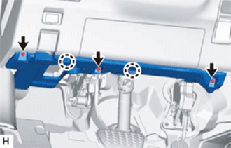
REMOVE LOWER NO. 1 INSTRUMENT PANEL AIRBAG ASSEMBLY
CAUTION:
When storing the lower No. 1 instrument panel airbag assembly, keep the airbag deployment side facing upward.
-
Check that the power switch is off.
-
Check that the cable is disconnected from the negative (-) auxiliary battery terminal.
CAUTION:
Wait at least 90 seconds after disconnecting the cable from the negative (-) auxiliary battery terminal to disable the SRS system.
-
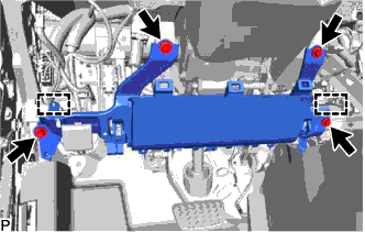
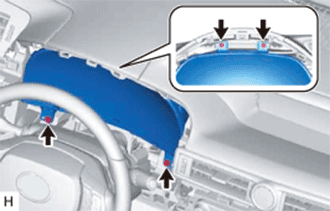
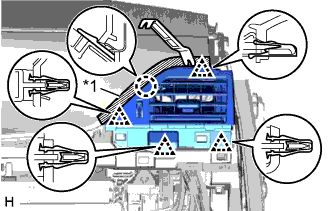
Remove the 4 bolts.
-
Detach the hook and pin to separate the lower No. 1 instrument panel airbag assembly.
Note
When separating the lower No. 1 instrument panel airbag assembly, do not pull the airbag wire harness.
-
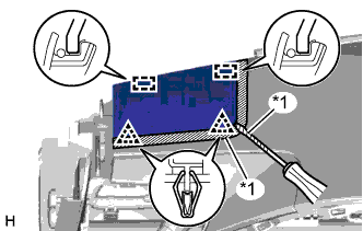
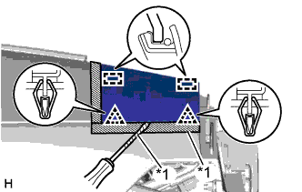
Detach the 3 claws to disconnect the hood lock control lever sub-assembly from the lower No. 1 instrument panel airbag assembly.
-
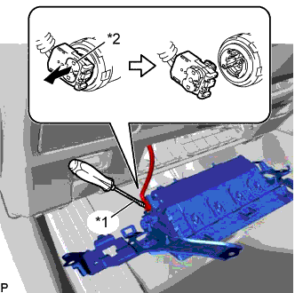
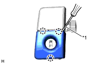
Using a screwdriver with the tip wrapped with protective tape, release the airbag connector lock.
-
Disconnect the airbag connector to remove the lower No. 1 instrument panel airbag assembly.
Text in Illustration *1 Protective Tape *2 Connector Lock Note
When disconnecting any airbag connector, take care not to damage the airbag wire harness.
-
-
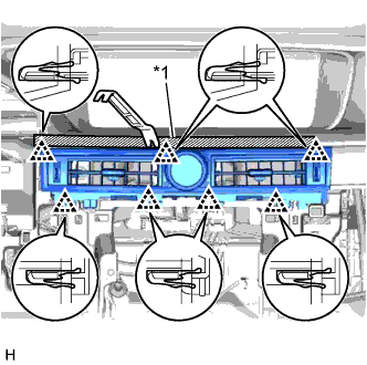
REMOVE INSTRUMENT CLUSTER FINISH PANEL ASSEMBLY
-
Detach the 9 clips and 2 guides and remove the instrument cluster finish panel assembly.
-
-
REMOVE INSTRUMENT CLUSTER FINISH PANEL SUB-ASSEMBLY
-
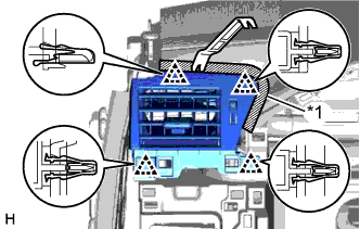
Detach the 6 clips and 6 claws.
-
Disconnect the connectors and remove the instrument cluster finish panel sub-assembly.
-
-
REMOVE HEADLIGHT DIMMER SWITCH ASSEMBLY
-
REMOVE COMBINATION METER ASSEMBLY
-
Remove the 4 screws.
-
Disconnect the connectors, detach the clamp and remove the combination meter assembly.
-
-
REMOVE NO. 1 INSTRUMENT PANEL REGISTER ASSEMBLY
Text in Illustration *1 Protective Tape
-
Put protective tape around the No. 1 instrument panel register assembly.
-
Using a moulding remover, detach the 4 clips.
-
Disconnect the connector and remove the No. 1 instrument panel register assembly.
-
-
REMOVE INSTRUMENT SIDE PANEL RH
Text in Illustration *1 Protective Tape
-
Put protective tape around the instrument side panel RH.
-
Using a moulding remover, detach the 7 clips and remove the instrument side panel RH.
-
w/ Airbag Cut Off Switch:
-
Disconnect the connector.
-
-
-
REMOVE NO. 2 INSTRUMENT PANEL UNDER COVER SUB-ASSEMBLY
-
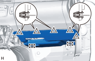
Detach the 5 clips and 2 guides.
-
Disconnect the connectors, detach the clamp and remove the No. 2 instrument panel under cover sub-assembly.
-
-
REMOVE GLOVE COMPARTMENT DOOR ASSEMBLY
Text in Illustration *1 Screw <A> *2 Bolt <E>
-
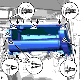
Remove the 3 screws <A> and 2 bolts <E>.
-
Detach the 6 clips.
-
Disconnect the connectors, detach the clamp and remove the glove compartment door assembly.
-
-
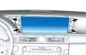
REMOVE MULTI-MEDIA MODULE RECEIVER ASSEMBLY
-
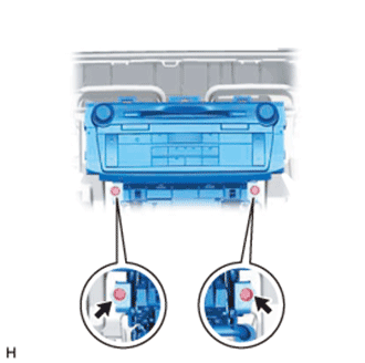
Remove the 2 bolts.
-
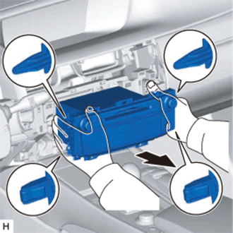
Detach the 2 claws and 2 clips.
-
Pull out the multi-media module receiver assembly.
-
Disconnect the connectors and remove the multi-media module receiver assembly.
-
-
REMOVE NO. 2 INSTRUMENT PANEL REGISTER ASSEMBLY
Text in Illustration *1 Protective Tape
-
Put protective tape around the No. 2 instrument panel register assembly.
-
Using a moulding remover, detach the 7 clips.
-
Disconnect the connectors and remove the No. 2 instrument panel register assembly.
-
-
REMOVE TELEMATICS TRANSCEIVER (w/ Telematics Transceiver)
-
Remove the 3 bolts and telematics transceiver with bracket.
-
Disconnect the connectors.
-
-
REMOVE NO. 2 INSTRUMENT PANEL GARNISH SUB-ASSEMBLY
Text in Illustration *1 Protective Tape
-
Put protective tape around the No. 2 instrument panel garnish sub-assembly.
-
Remove the 2 screws <G> from the back of the No. 2 instrument panel garnish sub-assembly.
-
Using a moulding remover, detach the 8 clips and remove the No. 2 instrument panel garnish sub-assembly.
-
-
REMOVE NO. 3 INSTRUMENT PANEL REGISTER ASSEMBLY
Text in Illustration *1 Protective Tape
-
Put protective tape around the No. 3 instrument panel register assembly.
-
Using a moulding remover, detach the 4 clips and claw.
-
Disconnect the connector and remove the No. 3 instrument panel register assembly.
-
-
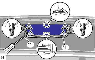
REMOVE NO. 1 INSTRUMENT PANEL SPEAKER PANEL SUB-ASSEMBLY
Text in Illustration *1 Protective Tape
-
Put protective tape around the No. 1 instrument panel speaker panel sub-assembly.
-
Using a screwdriver, detach the 2 clips and 2 guides and remove the No. 1 instrument panel speaker panel sub-assembly.
Tech Tips
Tape the screwdriver tip before use.
-
-
REMOVE NO. 2 INSTRUMENT PANEL SPEAKER PANEL SUB-ASSEMBLY
Text in Illustration *1 Protective Tape
-
Put protective tape around the No. 2 instrument panel speaker panel sub-assembly.
-
Using a screwdriver, detach the 2 clips and 2 guides and remove the No. 2 instrument panel speaker panel sub-assembly.
Tech Tips
Tape the screwdriver tip before use.
-
-
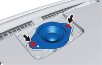
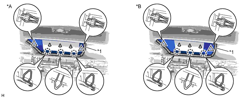
REMOVE FRONT NO. 2 SPEAKER ASSEMBLY
-
Remove the 2 screws.
-
Lift up the front No. 2 speaker assembly, disconnect the connector on the back of the speaker and remove the speaker.
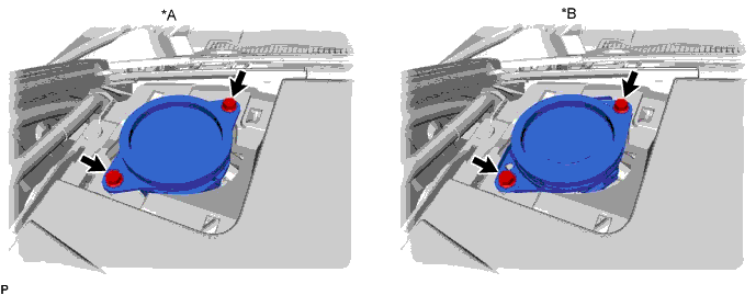
Text in Illustration *A w/o Mark Levinson Speaker System *B w/ Mark Levinson Speaker System Note
Do not touch the cone of the speaker.
Tech Tips
-
Use the same procedure for the RH and LH sides.
-
The procedure listed above is for the LH side.
-
-
-
REMOVE NO. 1 SPEAKER OPENING COVER ASSEMBLY
Text in Illustration *1 Protective Tape
-
Put protective tape around the No. 1 speaker opening cover assembly.
-
Using a screwdriver, detach the claw, 4 clips and guide and remove the No. 1 speaker opening cover assembly.
Tech Tips
Tape the screwdriver tip before use.
-
-
REMOVE FRONT NO. 3 SPEAKER ASSEMBLY
-
Remove the 2 screws.
-
Lift up the front No. 3 speaker assembly, disconnect the connector on the back of the speaker and remove the speaker.
Note
Do not touch the cone of the speaker.
-
-
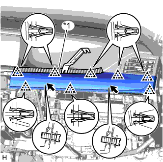
REMOVE UPPER INSTRUMENT CLUSTER FINISH PANEL
-
Put protective tape around the upper instrument cluster finish panel.
-
Remove the 3 clips <B>.
-
Detach the 2 clips and 3 claws and remove the upper instrument cluster finish panel.
Text in Illustration *A for 12.3 Inch *B for 8 Inch *1 Protective Tape - -
-
-
REMOVE ACCESSORY METER ASSEMBLY (for 12.3 Inch)
-
Remove the 4 bolts.
-
Disconnect the connectors and remove the accessory meter assembly.
-
-
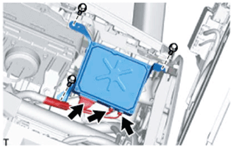
REMOVE MULTI-DISPLAY (for 8 Inch)
-
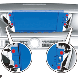
Remove the 4 screws.
-
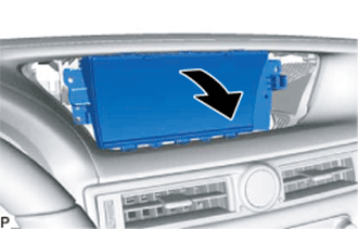
Move the multi-display in the direction of the arrow in the illustration.
-
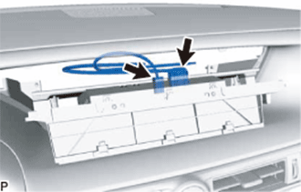
Disconnect all the connectors and remove multi-display.
-
-
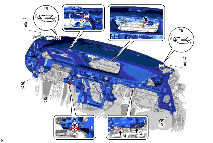
REMOVE INSTRUMENT PANEL SAFETY PAD SUB-ASSEMBLY
-
w/ Headup Display:
-
Disconnect the connectors and detach the clamp.
-
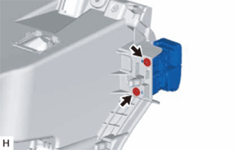
Detach the 2 claws and disconnect the room temperature sensor.
-
Remove the 2 bolts <C>, nut <D> and 2 bolts <E>.
-
Remove the 2 passenger airbag bolts <F>.
-
Detach the 2 guides and remove the instrument panel safety pad sub-assembly.
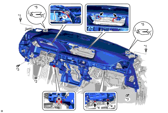
Text in Illustration *1 Bolt <C> *2 Nut <D> *3 Bolt <E> *4 Bolt <F> *5 Guide *6 Clamp
-
-
w/o Headup Display:
-
Disconnect the connectors and detach the clamp.
-
Detach the 2 claws and disconnect the room temperature sensor.
-
Remove the 2 bolts <C>, nut <D> and 2 bolts <E>.
-
Remove the 2 passenger airbag bolts <F>.
-
Detach the 2 guides and remove the instrument panel safety pad sub-assembly.
Text in Illustration *1 Bolt <C> *2 Nut <D> *3 Bolt <E> *4 Bolt <F> *5 Guide *6 Clamp
-
-
-
REMOVE GLOVE COMPARTMENT DOOR LOCK ASSEMBLY
-
Remove the 2 screws <A> and glove compartment door lock assembly.
-
-
REMOVE GLOVE COMPARTMENT DOOR LOCK COVER
Text in Illustration *1 Protective Tape
-
Using a screwdriver, detach the 3 claws and remove the glove compartment door lock cover.
Tech Tips
Tape the screwdriver tip before use.
-