REAR SUNSHADE SYSTEM Only Front Switch Cannot Operate Rear Sunshade
DESCRIPTION
The rear window shade assembly receives the rear sunshade switch assembly signals and drives its built-in motor.
WIRING DIAGRAM
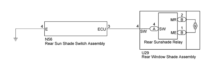
INSPECTION PROCEDURE
Note
-
Do not remove the ground bolt of the rear window shade assembly.
-
When the rear sunshade relay is replaced with a new one, do not use the wire harness packaged together with the new rear sunshade relay.
PROCEDURE
-
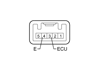
INSPECT REAR SUN SHADE SWITCH ASSEMBLY
-
Remove the rear sun shade switch assembly Click here.
-
Measure the resistance according to the value(s) in the table below.
Standard Resistance Tester Connection Switch Condition Specified Condition 3 (ECU) - 4 (E) Rear sun shade switch is pushed Below 1 Ω 3 (ECU) - 4 (E) Rear sun shade switch is not pushed 10 kΩ or higher
NG 
REPLACE REAR SUN SHADE SWITCH ASSEMBLY Click here
OK 
-
-
CHECK HARNESS AND CONNECTOR (REAR SUN SHADE SWITCH ASSEMBLY- REAR WINDOW SHADE ASSEMBLY AND BODY GROUND)
-
Disconnect the N56 rear sun shade switch assembly connector.
-
Disconnect the U29 rear window shade assembly connector.
-
Measure the resistance according to the value(s) in the table below.
Standard Resistance Tester Connection Condition Specified Condition N56-4 (E) - Body ground Always Below 1 Ω N56-3 (ECU) - U29-4 (SW) Always Below 1 Ω N56-3 (ECU) - Body ground Always 10 kΩ or higher
NG
REPAIR OR REPLACE HARNESS OR CONNECTOR
OK
-
-
INSPECT REAR WINDOW SHADE ASSEMBLY
-
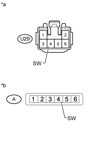
Text in Illustration *a Component without harness connected
(Rear Window Shade Assembly)
*b Component without harness connected
(Rear Sunshade Relay)
Remove the rear window shade assembly Click here.
-
Disconnect the rear window shade assembly connector.
-
Disconnect the rear sunshade relay connector.
-
Measure the resistance according to the value(s) in the table below.
Standard Resistance Tester Connection Condition Specified Condition U29-4 (SW) - A-4 (SW) Always Below 1 Ω U29-4 (SW) - Body ground Always 10 kΩ or higher
NG
REPLACE REAR WINDOW SHADE ASSEMBLY Click here
OK
-
-
CHECK REAR SUNSHADE RELAY
-
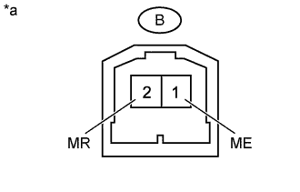
Text in Illustration *a Component with harness connected
(Rear Sunshade Relay)
Measure the voltage according to the value(s) in the table below.
Standard Voltage Tester Connection Condition Specified Condition B-2 (MR) - B-1 (ME) Rear sun shade switch assembly pushed (rear sunshade lowers from fully raised position) 11 to 14 V B-1 (ME) - B-2 (MR) Rear sun shade switch assembly pushed (rear sunshade raises from fully lowered position) 11 to 14 V
NG
REPLACE REAR SUNSHADE RELAY Click here
OK 
REPLACE REAR WINDOW SHADE ASSEMBLY Click here
-