AIR CONDITIONING AMPLIFIER REMOVAL

Tech Tips
-
Use the same procedure for RHD and LHD vehicles.
-
The procedure listed below is for LHD vehicles.
-
PRECAUTION
Note
-
After turning the power switch off, waiting time may be required before disconnecting the cable from the auxiliary battery terminal. Therefore, make sure to read the disconnecting the cable from the auxiliary battery terminal notice before proceeding with work Click here.
-
Before disconnecting the cable form the negative (-) auxiliary battery terminal or replacing the air conditioning amplifier assembly, record the last operation state of the air conditioning for each transmitter. After replacement, it is necessary to perform memory registration for each transmitter Click here.
-
-
DISCONNECT CABLE FROM AUXILIARY BATTERY NEGATIVE TERMINAL
CAUTION:
Wait at least 90 seconds after disconnecting the cable from the negative (-) auxiliary battery terminal to disable the SRS system.
Note
When disconnecting the cable, some systems need to be initialized after the cable is reconnected Click here.
-
REMOVE CENTER INSTRUMENT CLUSTER FINISH PANEL
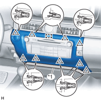
Text in Illustration *1 Protective Tape
-
Put protective tape around the center instrument cluster finish panel.
-
Detach the 9 clips and guide.
-
Disconnect the connector and remove the center instrument cluster finish panel.
-
-
REMOVE FRONT DOOR SCUFF PLATE RH
Tech Tips
Use the same procedure described for the LH side.
-
REMOVE INSTRUMENT SIDE PANEL RH
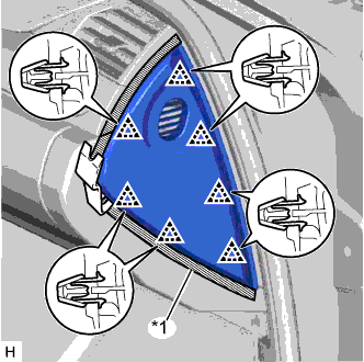
Text in Illustration *1 Protective Tape
-
Put protective tape around the instrument side panel RH.
-
Using a moulding remover, detach the 7 clips and remove the instrument side panel RH.
-
w/ Airbag Cut Off Switch:
-
Disconnect the connector.
-
-
-
REMOVE FRONT DOOR OPENING TRIM COVER RH
Tech Tips
Use the same procedure described for the LH side.
-
REMOVE INSTRUMENT PANEL FINISH PANEL END RH
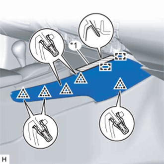
Text in Illustration *1 Protective Tape
-
Put protective tape around the instrument panel finish panel end RH.
-
Detach the 5 clips and 2 guides and remove the instrument panel finish panel end RH.
-
-
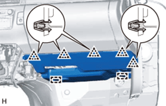
REMOVE NO. 2 INSTRUMENT PANEL UNDER COVER SUB-ASSEMBLY
-
Detach the 5 clips and 2 guides.
-
Disconnect the connectors, detach the clamp and remove the No. 2 instrument panel under cover sub-assembly.
-
-
REMOVE GLOVE COMPARTMENT DOOR ASSEMBLY
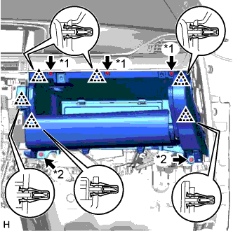
Text in Illustration *1 Screw <A> *2 Bolt <E>
-
Remove the 3 screws <A> and 2 bolts <E>.
-
Detach the 6 clips.
-
Disconnect the connectors, detach the clamp and remove the glove compartment door assembly.
-
-
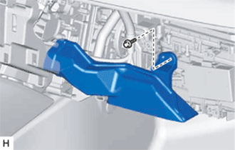
REMOVE NO. 2 AIR DUCT SUB-ASSEMBLY
-
Remove the screw and No. 2 air duct sub-assembly.
-
-
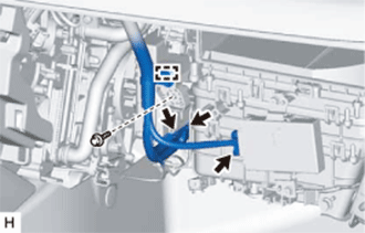
REMOVE AIR CONDITIONING AMPLIFIER ASSEMBLY
-
Disconnect the connectors.
-
Detach the clamp.
-
Remove the screw and air conditioning amplifier assembly.
-