COMPRESSOR (for 2GR-FXE) INSTALLATION

-
ADJUST COMPRESSOR OIL
-
When replacing the compressor with motor assembly with a new one, after gradually discharging the refrigerant gas from the service valve, drain the following volume of oil from the new compressor with motor assembly before installation.
Standard (Oil capacity inside a new compressor with motor assembly: 120 + 15 cc (4.06 + 0.51 fl. oz.)) - (Remaining oil amount in the removed compressor with motor assembly)) = Oil amount to be removed from the new compressor with motor assembly. Note
-
When checking the compressor oil level, follow the A/C system's precautions.
-
If a new compressor with motor assembly is installed without removing some oil remaining in the pipes of the vehicle, the oil amount becomes excessive. This prevents heat exchange in the refrigerant cycle and causes refrigerant failure.
-
If the volume of oil remaining in the removed compressor with motor assembly and magnetic clutch is too small, check for oil leakage.
-
Be sure to use ND-OIL 11 for compressor oil.
-
-
-
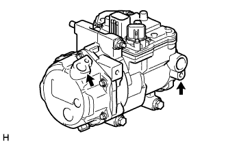
INSTALL COMPRESSOR WITH MOTOR ASSEMBLY
-
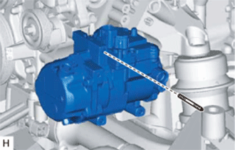
Using an E8 "TORX" socket, install the compressor with motor assembly with the stud bolt.
- Torque:
- 10 N*m { 102 kgf*cm, 7 ft.*lbf }
-
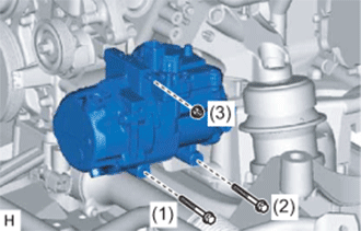
Install the compressor with motor assembly with the 2 bolts and nut.
- Torque:
- 25 N*m { 250 kgf*cm, 18 ft.*lbf }
Note
Tighten the bolts in the order shown in the illustration to install the compressor with motor assembly.
-
-
INSTALL NO. 1 COOLER REFRIGERANT DISCHARGE HOSE
-
Remove the attached vinyl tape from the No. 1 cooler refrigerant discharge hose.
-
Apply sufficient compressor oil (ND-OIL 11) to a new O-ring and the fitting surface of the compressor with motor assembly.
Compressor oil ND-OIL 11 or equivalent -
Install the O-ring on the No. 1 cooler refrigerant discharge hose.
-
Install the No. 1 cooler refrigerant discharge hose on the compressor with motor assembly with the bolt.
- Torque:
- 9.8 N*m { 100 kgf*cm, 87 in.*lbf }
-
-
INSTALL SUCTION HOSE
-
Remove the attached vinyl tape from the suction hose.
-
Apply sufficient compressor oil (ND-OIL 11) to a new O-ring and the fitting surface of the compressor with motor assembly.
Compressor oil ND-OIL 11 or equivalent -
Install the O-ring on the suction hose.
-
Install the suction hose on the compressor with motor assembly with the bolt.
- Torque:
- 9.8 N*m { 100 kgf*cm, 87 in.*lbf }
-
-
INSTALL ENGINE ROOM ECU BOX
-
INSTALL REAR ENGINE UNDER COVER LH
-
Install the rear engine under cover LH with the screw.
-
-
INSTALL ENGINE UNDER COVER
-
Install the engine under cover with the 13 screws and 3 clips.
-
-
INSTALL NO. 1 AIR CLEANER INLET
-
Install the No. 1 air cleaner inlet with the bolt.
- Torque:
- 5.0 N*m { 51 kgf*cm, 44 in.*lbf }
-
-
INSTALL SERVICE PLUG GRIP
-
INSTALL V-BANK COVER SUB-ASSEMBLY
-
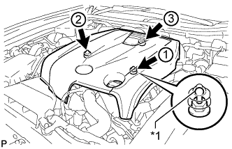
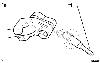
Text in Illustration *1 Tip (Round Portion) Attach the 3 clips in the order shown in the illustration to install the V-bank cover.
Note
-
Securely attach the clips.
-
If the clips are forcibly attached or struck with an object, they may be damaged.
-
Do not apply any oil to the tips (round portions).
-
-
-
CHARGE AIR CONDITIONING SYSTEM WITH REFRIGERANT
-
Perform vacuum purging using a vacuum pump or appropriate equipment.
-
Charge the air conditioning system with refrigerant.
Refrigerant type HFC-134a (R134a) 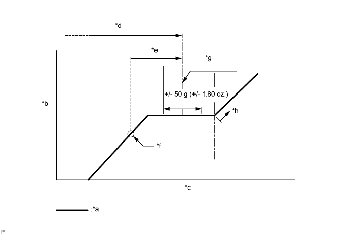
Text in Illustration *a Sub-cool System *b High Pressure *c Refrigerant Amount *d Standard charge amount *e Charge additional 100 g (3.5 oz.) *f Point where bubbles disappear *g Mean value in proper range *h Overcharged Standard charge amount for 2GR-FXE 450 to 550 g (15.9 to 19.4 oz.) for 2AR-FSE 520 to 620 g (18.3 to 21.8 oz.) - SST
- 09985-20010 ( 09985-02010, 09985-02050, 09985-02060, 09985-02070, 09985-02080, 09985-02090, 09985-02110, 09985-02130, 09985-02140, 09985-02150 )
Note
-
Do not turn the A/C switch on before charging the air conditioning system with refrigerant. Doing so may cause the compressor to work without refrigerant, resulting in overheating of the compressor.
-
The refrigerant amount should be checked by quantity (weight).
Tech Tips
Make sure that sufficient refrigerant is available to recharge the system when using a refrigerant recovery unit. Refrigerant recovery units are not always able to recover 100% of the refrigerant from an air conditioning system.
-
-
WARM UP COMPRESSOR
-
Keep the A/C switch on for at least 2 minutes to warm up the compressor.
Note
To prevent damage to the compressor, be sure to warm up the compressor when turning the air conditioning on after removing and installing air conditioning system lines (including the compressor).
-
-
CHECK FOR REFRIGERANT GAS LEAK
-
After recharging the air conditioning system with refrigerant, check for refrigerant leaks using a halogen leak detector.
-
Carry out the test under the following conditions:
-
Power switch off.
-
Secure good ventilation (the halogen leak detector may react to volatile gases which are not refrigerant, such as gasoline vapor and exhaust gas).
-
Repeat the inspection 2 or 3 times.
-
Measure the pressure to make sure that there is some refrigerant remaining in the air conditioning system (pressure when the compressor is off: approx. 392 to 588 kPa (3.9 to 5.9 kgf/cm2, 57 to 85 psi)).
-
-
Text in Illustration *1 Halogen Leak Detector *a Check for Leak Using a halogen leak detector, check for refrigerant leaks from the air conditioning system.
-
If a refrigerant leak is not detected from the drain hose, remove the blower motor control from the cooling unit. Insert the halogen leak detector sensor into the unit and check for a leak.
-
Disconnect the pressure sensor connector and leave it for approximately 20 minutes. Bring the halogen leak detector close to the pressure sensor and check for a leak.
Tech Tips
When checking for leaks, the presence of oily dirt at a joint can indicate a leak.
-
-
INSTALL COOL AIR INTAKE DUCT SEAL
-
Install the cool air intake duct seal with the 7 clips.
-
-
INSTALL ENGINE ROOM SIDE COVER LH
-
Install the engine room side cover with the 4 clips.
-