SOLAR SENSOR ON-VEHICLE INSPECTION

-
CHECK AIR CONDITIONING SOLAR SENSOR
-
Disconnect the A/C solar sensor connector.
-
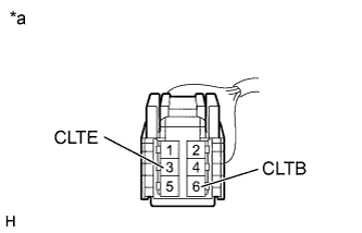
Text in Illustration *a Front view of wire harness connector
(to Automatic Light Control Sensor (Solar Sensor))
Turn the power switch on (IG).
-
Measure the voltage according to the value(s) in the table below.
Standard Voltage Tester Connection Condition Specified Condition 6(CLTB) - 3(CLTE) IG OFF Below 1 V 6(CLTB) - 3(CLTE) IG ON 11 to 14 V If the result is not as specified, repair or replace the wire harness or connector.
-
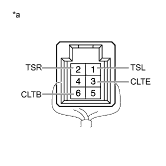
Text in Illustration *a Component with harness connected
(Automatic Light Control Sensor (Solar Sensor ))
Remove the A/C solar sensor with the connector still connected.
-
Apply auxiliary battery voltage between terminals 6 (CLTB) and 3 (CLTE) of the A/C solar sensor.
-
Measure the voltage according to the value(s) in the table below.
Standard Voltage Tester Connection Condition Specified Condition 1(TSL) - 3(CLTE) Sensor is exposed to electric light 0.8 to 4.3 V 1(TSL) - 3(CLTE) Sensor is covered with a cloth Below 0.8 V 2(TSR) - 3(CLTE) Sensor is exposed to electric light 0.8 to 4.3 V 2(TSR) - 3(CLTE) Sensor is covered with a cloth Below 0.8 V Tech Tips
-
As the inspection light is moved away from the sensor, the voltage increases.
-
Use an incandescent lamp for inspection. Bring it about 30 cm (11.8 in.) from the solar sensor.
If the result is not as specified, replace the automatic light control sensor (solar sensor).
-
-