SPIRAL CABLE INSTALLATION

-
INSPECT SPIRAL CABLE SUB-ASSEMBLY
Note
If the steering sensor is installed to a misaligned spiral cable sub-assembly, DTCs for an abnormal steering sensor value such as DTC C1290, C1439 and DTC C1445 are stored and it is impossible to repair them. If this happens, replace the spiral cable with sensor sub-assembly with a new one.
-
Check if the spiral cable sub-assembly is centered.
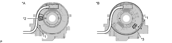
Text in Illustration *A w/o Steering Heater *B w/ Steering Heater *1 Alignment Mark *2 Colored Roller (Yellow) *3 Flat Cable - - Tech Tips
When the spiral cable sub-assembly is centered, the alignment marks are aligned and the colored roller (yellow) or flat cable shown in the illustration is visible.
-
If the spiral cable sub-assembly is not centered, center it.
If the cable cannot be centered, it is possible that the spiral cable sub-assembly is broken. Replace the spiral cable with sensor sub-assembly with a new one.
-
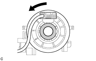
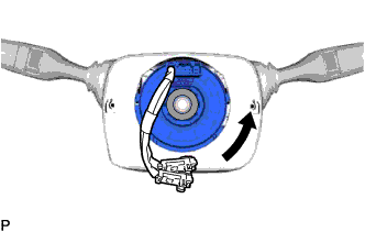
While pushing on the interlock indicated in the illustration, rotate the spiral cable sub-assembly counterclockwise slowly by hand until it stops.
Text in Illustration 
Interlock Note
-
When rotating the spiral cable sub-assembly, make sure to push on the interlock indicated in the illustration to release the interlock mechanism.
-
Do not turn the spiral cable sub-assembly using the airbag wire harness.
-
-
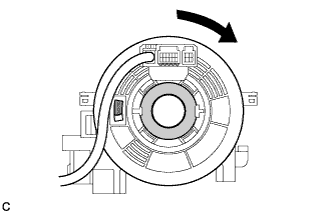
Rotate the spiral cable sub-assembly approximately 2.5 rotations in the clockwise direction from the locked position until the colored roller (yellow) or flat cable can be seen, and then align the alignment marks.
Tech Tips
The spiral cable sub-assembly will rotate approximately 2.5 turns to both the left and right from the center.
-
-
-
INSTALL SPIRAL CABLE SUB-ASSEMBLY
-
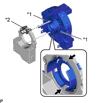
Text in Illustration *1 Pin *2 Lock Pin Align the 2 pins of the spiral cable sub-assembly with the locations shown in the illustration and attach the 6 claws to install the spiral cable sub-assembly to the steering sensor.
Note
Do not remove the lock pin before the spiral cable sub-assembly is installed to the steering sensor.
-
Remove the lock pin from the steering sensor.
-
-
INSTALL SPIRAL CABLE WITH SENSOR SUB-ASSEMBLY
Note
-
Do not replace the spiral cable with the auxiliary battery connected and the power switch on (IG).
-
Do not rotate the spiral cable with the auxiliary battery connected and the power switch on (IG).
-
Ensure that the steering wheel is installed and aligned straight when inspecting the steering sensor.
-
Check that the power switch is off.
-
Check that the cable is disconnected from the negative (-) auxiliary battery terminal.
CAUTION:
Wait at least 90 seconds after disconnecting the cable from the negative (-) auxiliary battery terminal to disable the SRS system.
-
Check that the front wheels are facing straight ahead.
-
Install the spiral cable with sensor sub-assembly with the 3 claws.
Note
When replacing the spiral cable with sensor sub-assembly with a new one, remove the lock pin before installing the steering wheel assembly.
-
Connect the connectors to the spiral cable with sensor sub-assembly.
Note
When connecting any airbag connector, take care not to damage the airbag wire harness.
-
-
INSTALL STEERING COLUMN COVER (w/ Driver Monitor Camera)
-
Connect the connector.
-
Attach the 2 claws to install the steering column upper cover.
-
Attach the 4 clips.
-
Attach the 2 claws to install the steering column lower cover.
Note
Do not damage the tilt and telescopic switch.
-
Install the 3 screws.
-
-
INSTALL STEERING COLUMN COVER (w/o Driver Monitor Camera)
-
Attach the 2 claws to install the steering column upper cover.
-
Attach the 4 clips.
-
Attach the 2 claws to install the steering column lower cover.
Note
Do not damage the tilt and telescopic switch.
-
Install the 3 screws.
-
-
TURN FRONT WHEELS TO FACE STRAIGHT AHEAD
-
ADJUST SPIRAL CABLE WITH SENSOR SUB-ASSEMBLY
Note
Do not adjust the spiral cable with the auxiliary battery connected and the power switch on (IG).
-
Check that the power switch is off.
-
Check that the cable is disconnected from the negative (-) auxiliary battery terminal.
CAUTION:
Wait at least 90 seconds after disconnecting the cable from the negative (-) auxiliary battery terminal to disable the SRS system.
-
Check if the spiral cable sub-assembly is centered.
Text in Illustration *A w/o Steering Heater *B w/ Steering Heater *1 Alignment Mark *2 Colored Roller (Yellow) *3 Flat Cable - - Tech Tips
When the spiral cable sub-assembly is centered, the alignment marks are aligned and the colored roller (yellow) or flat cable shown in the illustration is visible.
-
If the spiral cable sub-assembly is not centered, center it.
-
While pushing on the interlock indicated in the illustration, rotate the spiral cable sub-assembly counterclockwise slowly by hand until it stops.
Text in Illustration Interlock Note
-
When rotating the spiral cable sub-assembly, make sure to push on the interlock indicated in the illustration to release the interlock mechanism.
-
Do not turn the spiral cable sub-assembly using the airbag wire harness.
-
-

While pushing on the interlock indicated, rotate the spiral cable sub-assembly clockwise approximately 2.5 turns to the position where the colored roller (yellow) or flat cable is visible.
Text in Illustration Interlock Note
-
When rotating the spiral cable sub-assembly, make sure to push on the interlock indicated in the illustration to release the interlock mechanism.
-
Do not turn the spiral cable sub-assembly using the airbag wire harness.
Tech Tips
The spiral cable will rotate approximately 2.5 turns to both the left and right from the center.
-
-
-
INSTALL STEERING WHEEL ASSEMBLY
-
ENABLE AUTOAWAY/RETURN FUNCTION
-
Restore the autoaway/return function setting to the previous condition by changing the customize parameter Click here.
-