SPIRAL CABLE INSPECTION

-
INSPECT SPIRAL WITH SENSOR CABLE SUB-ASSEMBLY (w/o Steering Heater)
-
Visually check for defects with the spiral cable removed from the vehicle.
-
The defects are as follows:
-
Scratches on the spiral cable
-
Small cracks on the spiral cable
-
Dents on the spiral cable
-
Chips on the spiral cable
-
Cracks or other damage to the connector
OK No defects are found.
Tech Tips
If any of the defects is found, replace the spiral cable with sensor sub-assembly new a one.
-
-
-
Inspect the spiral cable.
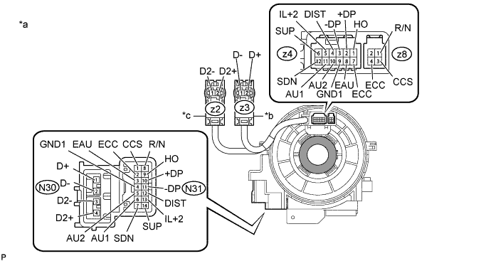
Text in Illustration *a Component without harness connected
(Spiral Cable Sub-assembly)
*b Color: Orange *c Color: Black - - 
Interlock - -
-
Measure the resistance according to the value(s) in the table below.
Note
-
When rotating the spiral cable, make sure to push on the interlock indicated in the illustration to release the interlock mechanism.
-
To avoid breakage of the spiral cable, do not turn the spiral cable more than necessary.
Standard Resistance Tester Connection Condition Specified Condition N30-1 (D+) - z3-2 (D+) Center Less than 1 Ω 2.5 rotations to the left 2.5 rotations to the right N30-2 (D-) - z3-1 (D-) Center Less than 1 Ω 2.5 rotations to the left 2.5 rotations to the right N30-3 (D2-) - z2-1 (D2-) Center Less than 1 Ω 2.5 rotations to the left 2.5 rotations to the right N30-4 (D2+) - z2-2 (D2+) Center Less than 1 Ω 2.5 rotations to the left 2.5 rotations to the right N31-1 (CCS) - z8-3 (CCS) Center Below 3 Ω 2.5 rotations to the left 2.5 rotations to the right N31-2 (ECC) - z8-4 (ECC) Center Below 3 Ω 2.5 rotations to the left 2.5 rotations to the right N31-2 (ECC) - z4-7 (ECC) Center Below 3 Ω 2.5 rotations to the left 2.5 rotations to the right N31-3 (EAU) - z4-8 (EAU) Center Below 3 Ω 2.5 rotations to the left 2.5 rotations to the right N31-4 (GND1) - z4- 9 (GND1) Center Below 3 Ω 2.5 rotations to the left 2.5 rotations to the right N31-5 (AU2) - z4-10 (AU2) Center Below 3 Ω 2.5 rotations to the left 2.5 rotations to the right N31-6 (AU1) - z4-11 (AU1) Center Below 3 Ω 2.5 rotations to the left 2.5 rotations to the right N31-7 (SDN) - z4-12 (SDN) Center Below 3 Ω 2.5 rotations to the left 2.5 rotations to the right N31-8 (R/N) - z8-1 (R/N) Center Below 3 Ω 2.5 rotations to the left 2.5 rotations to the right N31-9 (HO) - z4-1 (HO) Center Below 3 Ω 2.5 rotations to the left 2.5 rotations to the right N31-10 (+DP) - z4-2 (+DP) Center Below 3 Ω 2.5 rotations to the left 2.5 rotations to the right N31-11 (-DP) - z4-3 (-DP) Center Below 3 Ω 2.5 rotations to the left 2.5 rotations to the right If the value is not within the specified range, replace the spiral cable with sensor sub-assembly.
-
-
-
-
INSPECT SPIRAL CABLE SUB-ASSEMBLY (w/ Steering Heater)
-
Visually check for defects with the spiral cable removed from the vehicle.
-
The defects are as follows:
-
Scratches on the spiral cable
-
Small cracks on the spiral cable
-
Dents on the spiral cable
-
Chips on the spiral cable
-
Cracks or other damage to the connector
OK No defects are found.
Tech Tips
If any of the defects is found, replace the spiral cable with a new one.
-
-
-
Inspect the spiral cable.
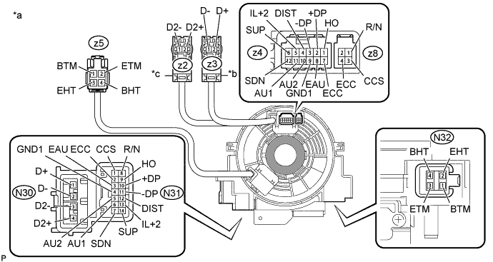
Text in Illustration *a Component without harness connected
(Spiral Cable Sub-assembly)
*b Color: Orange *c Color: Black - - Interlock - -
-
Measure the resistance according to the value(s) in the table below.
Note
-
When rotating the spiral cable, make sure to push on the interlock indicated in the illustration to release the interlock mechanism.
-
To avoid breakage of the spiral cable, do not turn the spiral cable more than necessary.
Standard Resistance Tester Connection Condition Specified Condition N30-1 (D+) - z3-2 (D+) Center Less than 1 Ω 2.5 rotations to the left 2.5 rotations to the right N30-2 (D-) - z3-1 (D-) Center Less than 1 Ω 2.5 rotations to the left 2.5 rotations to the right N30-3 (D2-) - z2-1 (D2-) Center Less than 1 Ω 2.5 rotations to the left 2.5 rotations to the right N30-4 (D2+) - z2-2 (D2+) Center Less than 1 Ω 2.5 rotations to the left 2.5 rotations to the right N31-1 (CCS) - z8-3 (CCS) Center Below 3 Ω 2.5 rotations to the left 2.5 rotations to the right N31-2 (ECC) - z8-4 (ECC) Center Below 3 Ω 2.5 rotations to the left 2.5 rotations to the right N31-2 (ECC) - z4-7 (ECC) Center Below 3 Ω 2.5 rotations to the left 2.5 rotations to the right N31-3 (EAU) - z4-8 (EAU) Center Below 3 Ω 2.5 rotations to the left 2.5 rotations to the right N31-4 (GND1) - z4- 9 (GND1) Center Below 3 Ω 2.5 rotations to the left 2.5 rotations to the right N31-5 (AU2) - z4-10 (AU2) Center Below 3 Ω 2.5 rotations to the left 2.5 rotations to the right N31-6 (AU1) - z4-11 (AU1) Center Below 3 Ω 2.5 rotations to the left 2.5 rotations to the right N31-7 (SDN) - z4-12 (SDN) Center Below 3 Ω 2.5 rotations to the left 2.5 rotations to the right N31-8 (R/N) - z8-1 (R/N) Center Below 3 Ω 2.5 rotations to the left 2.5 rotations to the right N31-9 (HO) - z4-1 (HO) Center Below 3 Ω 2.5 rotations to the left 2.5 rotations to the right N31-10 (+DP) - z4-2 (+DP) Center Below 3 Ω 2.5 rotations to the left 2.5 rotations to the right N31-11 (-DP) - z4-3 (-DP) Center Below 3 Ω 2.5 rotations to the left 2.5 rotations to the right N31-12 (DIST) - z4- 4 (DIST) Center Below 3 Ω 2.5 rotations to the left 2.5 rotations to the right N31-13 (IL+2) - z4-5 (IL+2) Center Below 3 Ω 2.5 rotations to the left 2.5 rotations to the right N31-14 (SUP) - z4-6 (SUP) Center Below 3 Ω 2.5 rotations to the left 2.5 rotations to the right N32-2 (EHT) - z5-3 (EHT) Center Below 3 Ω 2.5 rotations to the left 2.5 rotations to the right N32-4 (BHT) - z5-4 (BHT) Center Below 3 Ω 2.5 rotations to the left 2.5 rotations to the right N32-1 (BTM) - z5-1 (BTM) Center Less than 0.1 Ω 2.5 rotations to the left 2.5 rotations to the right N32-3 (ETM) - z5-2 (ETM) Center Less than 0.1 Ω 2.5 rotations to the left 2.5 rotations to the right If the value is not within the specified range, replace the spiral cable with sensor sub-assembly.
-
-
-