SPIRAL CABLE REMOVAL

-
DISABLE AUTO TILT AWAY FUNCTION
-
Disable the autoaway/return function by changing the customize parameter Click here
CAUTION:
Record the current customize parameter setting (whether the autoaway/return function is enabled or disabled) in order to restore the current setting after finishing the operation.
Tech Tips
Performing the above operation causes the autoaway/return function to be disabled when the power switch is turned off.
-
Turn the power switch on (IG). Operate the tilt and telescopic switch to fully extend and lower the steering column assembly.
-
Turn the power switch off.
-
-
REMOVE STEERING WHEEL ASSEMBLY
-
REMOVE STEERING COLUMN COVER (w/o Driver Monitor Camera)
-
Remove the 3 screws.
-
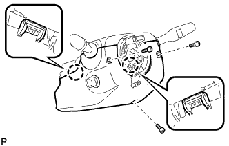
Detach the 2 claws to remove the steering column lower cover.
Note
Do not damage the tilt and telescopic switch.
-
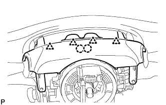
Detach the 4 clips.
-
Detach the 2 claws to remove the steering column upper cover.
-
-
REMOVE STEERING COLUMN COVER (w/ Driver Monitor Camera)
-
Remove the 3 screws.
-
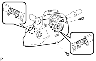
Detach the 2 claws to remove the steering column lower cover.
Note
Do not damage the tilt and telescopic switch.
-
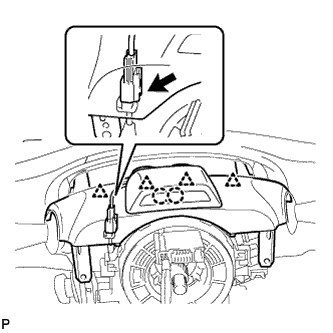
Detach the 4 clips.
-
Detach the 2 claws.
-
Disconnect the connectors and remove the steering column cover.
-
-
REMOVE SPIRAL CABLE WITH SENSOR SUB-ASSEMBLY
Note
-
Do not replace the spiral cable with the auxiliary battery connected and the power switch on (IG).
-
Do not rotate the spiral cable with the auxiliary battery connected and the power switch on (IG).
-
Ensure that the steering wheel is installed and aligned straight when inspecting the steering sensor.
-
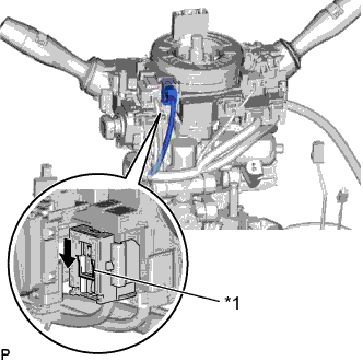
Text in Illustration *1 Slider Slide the slider to release the lock, and then disconnect the yellow airbag connector from the spiral cable with sensor sub-assembly.
Note
When disconnecting any airbag connector, take care not to damage the airbag wire harness.
-
Disconnect the other connector from the spiral cable with sensor sub-assembly.
-
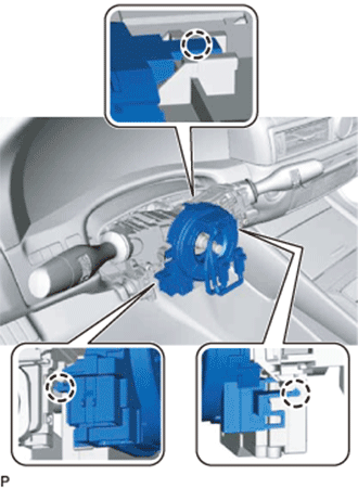
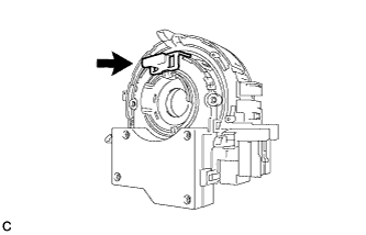
Disengage the 3 claws to remove the spiral cable with sensor sub-assembly.
-
-
REMOVE SPIRAL CABLE SUB-ASSEMBLY
Note
-
Remove the spiral cable sub-assembly from the steering sensor only when replacing it or the steering sensor.
-
Removing the steering sensor from the spiral cable sub-assembly without using a lock pin may result in a misaligned center position of the steering sensor. Therefore, make sure to use the lock pin provided with a new spiral cable sub-assembly or steering sensor when removing the steering sensor from the spiral cable sub-assembly.
-
Install the lock pin to the steering sensor.
Note
-
Use the lock pin provided with a new spiral cable sub-assembly.
-
Do not remove the lock pin before the spiral cable sub-assembly is installed to the steering sensor.
-
-
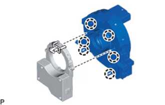
Detach the 6 claws to remove the spiral cable sub-assembly from the steering sensor.
-