LIGHT CONTROL RHEOSTAT INSPECTION

Tech Tips
-
Use the same procedure for RHD and LHD vehicles.
-
The procedure listed below is for LHD vehicles.
-
INSPECT TRIP SWITCH (LIGHT CONTROL RHEOSTAT)
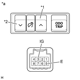
Text in Illustration *1 Up Switch *2 Down Switch *a Component without harness connected
{Trip Switch (Light Control Rheostat)}
-
Measure the resistance according to the value(s) in the table below.
Standard Resistance Tester Connection Switch Condition Specified Condition 3 (IG) - 5 (E) Up switch on
(Pushed)
Below 1 Ω 3 (IG) - 5 (E) Up switch off
(Not pushed)
10 kΩ or higher 3 (IG) - 5 (E) Down switch on
(Pushed)
1.7 to 1.8 kΩ 3 (IG) - 5 (E) Down switch off
(Not pushed)
10 kΩ or higher If the result is not as specified, replace the trip switch (light control rheostat).
-
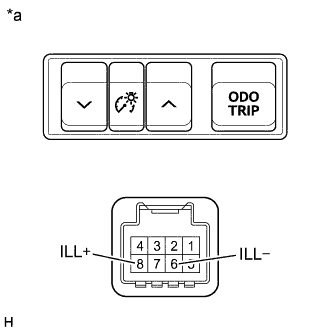
Text in Illustration *a Component without harness connected
{Trip Switch (Light Control Rheostat)}
Apply battery voltage to the connector and check the illumination condition.
OK Measurement Condition Specified Condition Battery positive (+) → Terminal 8 (ILL+)
Battery negative (-) → Terminal 6 (ILL-)
Illuminates If the result is not as specified, replace the trip switch (light control rheostat).
-