METER / GAUGE SYSTEM Headup Display Malfunction
DESCRIPTION
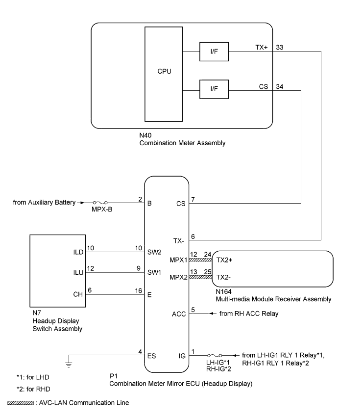
This circuit is the power source circuit for the headup display. This circuit provides two types of power sources; one is a constant power source mainly used as a backup power source, and the other is a power source mainly used for signal transmission.
WIRING DIAGRAM
INSPECTION PROCEDURE
Tech Tips
Before starting the following inspection, confirm the headup display position and illuminance, then perform the operation check Click here.
PROCEDURE
-
SYSTEM CHECK
-
Check the symptom of the headup display.
Result Result Proceed to Headup display does not operate at all. A Headup display does not change. B
B 
CONFIRM DTC OUTPUT (HEADUP DISPLAY) Click here
A 
-
-
INSPECT HEAD UP DISPLAY SWITCH ASSEMBLY
-
Remove the headup display switch assembly Click here.
-
Inspect the headup display switch assembly Click here.
NG 
REPLACE HEAD UP DISPLAY SWITCH ASSEMBLY Click here
OK
-
-
CHECK HARNESS AND CONNECTOR (COMBINATION METER MIRROR ECU - HEADUP DISPLAY SWITCH ASSEMBLY, BATTERY AND BODY GROUND)
-
Disconnect the P1 combination meter mirror ECU connector.
-
Disconnect the N7 headup display switch assembly connector.
-
Measure the resistance according to the value(s) in the table below.
Standard Resistance Tester Connection Condition Specified Condition P1-10 (SW2) - N7-10 (ILD) Always Below 1 Ω P1-9 (SW1) - N7-12 (ILU) P1-16 (E) - N7-6 (CH) P1-4 (ES) - Body ground P1-10 (SW2) - Body ground Always 10 kΩ or higher P1-9 (SW1) - Body ground P1-16 (E) - Body ground -
Measure the voltage according to the value(s) in the table below.
Standard Voltage Tester Connection Condition Specified Condition P1-1 (IG) - Body ground Power switch on (IG) 11 to 14 V Power switch off Below 1 V P1-2 (B) - Body ground Always 11 to 14 V P1-5 (ACC) - Body ground Power switch on (ACC) 11 to 14 V Power switch off Below 1 V
NG
REPAIR OR REPLACE HARNESS OR CONNECTOR
OK 
REPLACE COMBINATION METER MIRROR ECU Click here
-
-
CONFIRM DTC OUTPUT (HEADUP DISPLAY)
-
Confirm DTC output Click here.
Result Result Proceed to DTC is not output. A DTC (01, 02) is output. B DTC (03, 04) is output. C
B
CHECK HARNESS AND CONNECTOR (COMBINATION METER MIRROR ECU - COMBINATION METER ASSEMBLY) Click here
C
CHECK HARNESS AND CONNECTOR (COMBINATION METER MIRROR ECU - MULTI-MEDIA MODULE RECEIVER ASSEMBLY) Click here
A
-
-
CHECK COMBINATION METER ASSEMBLY
-
Temporarily replace the combination meter assembly with a new or normally functioning one Click here.
-
Check the headup display operation.
Result The operation of the headup display returns to normal.
NG
REPLACE COMBINATION METER MIRROR ECU Click here
OK
END (COMBINATION METER ASSEMBLY WAS DEFECTIVE)
-
-
CHECK HARNESS AND CONNECTOR (COMBINATION METER MIRROR ECU - COMBINATION METER ASSEMBLY)
-
Disconnect the P1 combination meter mirror ECU connector.
-
Disconnect the N40 combination meter assembly connector.
-
Measure the resistance according to the value(s) in the table below.
Standard Resistance Tester Connection Condition Specified Condition P1-6 (TX-) - N40-33 (TX+) Always Below 1 Ω P1-7 (CS) - N40-34 (CS) P1-6 (TX-) - Body ground Always 10 kΩ or higher P1-7 (CS) - Body ground
NG
REPAIR OR REPLACE HARNESS OR CONNECTOR
OK
-
-
CHECK COMBINATION METER ASSEMBLY
-
Temporarily replace the combination meter assembly with a new or normally functioning one Click here.
-
Check the headup display operation.
Result The operation of the headup display returns to normal.
NG
REPLACE COMBINATION METER MIRROR ECU Click here
OK
END (COMBINATION METER ASSEMBLY WAS DEFECTIVE)
-
-
CHECK HARNESS AND CONNECTOR (COMBINATION METER MIRROR ECU - MULTI-MEDIA MODULE RECEIVER ASSEMBLY)
-
Disconnect the P1 combination meter mirror ECU connector.
-
Disconnect the N164 multi-media module receiver assembly connector.
-
Measure the resistance according to the value(s) in the table below.
Standard Resistance Tester Connection Condition Specified Condition P1-12 (MPX1) - N164-24 (TX2+) Always Below 1 Ω P1-13 (MPX2) - N164-25 (TX2-) P1-12 (MPX1) - Body ground Always 10 kΩ or higher P1-13 (MPX2) - Body ground
NG
REPAIR OR REPLACE HARNESS OR CONNECTOR
OK
-
-
CHECK MULTI-MEDIA MODULE RECEIVER ASSEMBLY
-
Temporarily replace the multi-media module receiver assembly with a new or normally functioning one Click here.
-
Check the headup display operation.
Result The operation of the headup display returns to normal.
NG
REPLACE COMBINATION METER MIRROR ECU Click here
OK
END (MULTI-MEDIA MODULE RECEIVER ASSEMBLY WAS DEFECTIVE)
-