HEADUP DISPLAY SWITCH INSPECTION

Tech Tips
-
Use the same procedure for RHD and LHD vehicles.
-
The procedure listed below is for LHD vehicles.
-
INSPECT HEADUP DISPLAY SWITCH ASSEMBLY

Text in Illustration *1 HUD Switch *2 TILT Switch *3 RHEOSTAT Switch *4 DISP Switch *a Component without harness connected
(Headup Display Switch Assembly)
-
Measure the resistance according to the value(s) in the table below.
Standard Resistance Tester Connection Switch Condition Specified Condition 12 (ILU) - 6 (CH) HUD switch off
(Not pushed)
100 kΩ 10 (ILD) - 6 (CH) 100 kΩ 12 (ILU) - 6 (CH) HUD switch on
(Pushed)
Below 1 Ω 10 (ILD) - 6 (CH) 100 kΩ 12 (ILU) - 6 (CH) TILT switch (UP) on
(Pushed)
100 kΩ 10 (ILD) - 6 (CH) 3210 Ω 12 (ILU) - 6 (CH) TILT switch off
(Not pushed)
100 kΩ 10 (ILD) - 6 (CH) 100 kΩ 12 (ILU) - 6 (CH) TILT switch (DOWN) on
(Pushed)
100 kΩ 10 (ILD) - 6 (CH) 1010 Ω 12 (ILU) - 6 (CH) RHEOSTAT switch (ILL UP) on
(Pushed)
100 kΩ 10 (ILD) - 6 (CH) 330 Ω 12 (ILU) - 6 (CH) RHEOSTAT switch off
(Not pushed)
100 kΩ 10 (ILD) - 6 (CH) 100 kΩ 12 (ILU) - 6 (CH) RHEOSTAT switch (ILL DOWN) on
(Pushed)
100 kΩ 10 (ILD) - 6 (CH) Below 1 Ω 12 (ILU) - 6 (CH) DISP switch off
(Not pushed)
100 kΩ 10 (ILD) - 6 (CH) 100 kΩ 12 (ILU) - 6 (CH) DISP switch on
(Pushed)
330 Ω 10 (ILD) - 6 (CH) 100 kΩ If the result is not as specified, replace the headup display switch assembly.
-
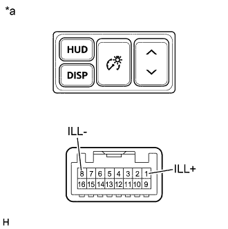
Text in Illustration *a Component without harness connected
(Headup Display Switch Assembly)
Apply battery voltage to the connector and check the illumination condition.
OK Measurement Condition Specified Condition Battery positive (+) → Terminal 1 (ILL+)
Battery negative (-) → Terminal 8 (ILL-)
Illuminates If the result is not as specified, replace the headup display switch assembly.
-