METER / GAUGE SYSTEM Fuel Gauge Malfunction
DESCRIPTION
The fuel sender gauge has a variable resistance mechanism. The resistance decreases when the fuel amount increases, and the resistance increases when the fuel amount decreases. The fuel receiver gauge changes based on the resistance of the fuel sender gauge.
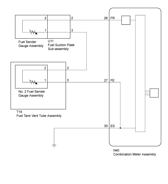
WIRING DIAGRAM
INSPECTION PROCEDURE
PROCEDURE
-
PERFORM ACTIVE TEST USING GTS (FUEL METER OPERATION)
-
Use the Active Test to check the operation of the fuel receiver gauge Click here.
Combination Meter Tester Display Test Part Control Range Diagnostic Note Fuel Meter Operation Fuel receiver gauge OFF, Empty, 1/2 or Full - OK Fuel receiver gauge indication is normal.
NG 
REPLACE COMBINATION METER ASSEMBLY Click here
OK 
-
-
READ VALUE USING GTS (FUEL INPUT)
-
Use the Data List to check if the fuel receiver gauge is operating properly Click here.
Combination Meter Tester Display Measurement Item/Range Normal Condition Diagnostic Note Fuel Input Fuel input signal / Min.: 0, Max.: 127.5 Current fuel level displayed Unit: Liters. OK Fuel level signal displayed on the GTS is almost the same as fuel receiver gauge indication.
NG
REPLACE COMBINATION METER ASSEMBLY Click here
OK
-
-
CHECK HARNESS AND CONNECTOR (COMBINATION METER ASSEMBLY - FUEL SUCTION PLATE SUB-ASSEMBLY, FUEL TANK VENT TUBE ASSEMBLY AND BODY GROUND)
-
Disconnect the N40 combination meter assembly connector.
-
Disconnect the U11 fuel suction plate sub-assembly connector.
-
Disconnect the T16 fuel tank vent tube assembly connector.
-
Measure the resistance according to the value(s) in the table below.
Standard Resistance Tester Connection Condition Specified Condition N40-26 (FR) - U11-2 Always Below 1 Ω N40-27 (FE) - T16-3 U11-3 - T16-2 N40-30 (ES) - Body ground N40-26 (FR) - Body ground Always 10 kΩ or higher N40-27 (FE) - Body ground U11-3 - Body ground
NG
REPAIR OR REPLACE HARNESS OR CONNECTOR
OK
-
-
INSPECT FUEL SENDER GAUGE ASSEMBLY
-
Remove the fuel sender gauge assembly.
-
w/ Canister Pump Module Click here.
-
w/o Canister Pump Module Click here.
-
-
Inspect the fuel sender gauge assembly.
-
w/ Canister Pump Module Click here.
-
w/o Canister Pump Module Click here.
Result Result Proceed to OK A NG (w/ Canister Pump Module) B NG (w/o Canister Pump Module) C
-
B
REPLACE FUEL SENDER GAUGE ASSEMBLY Click here
C
REPLACE FUEL SENDER GAUGE ASSEMBLY Click here
A
-
-
INSPECT FUEL SUCTION PLATE SUB-ASSEMBLY
-
Remove the fuel suction plate sub-assembly.
-
w/ Canister Pump Module Click here.
-
w/o Canister Pump Module Click here.
-
-
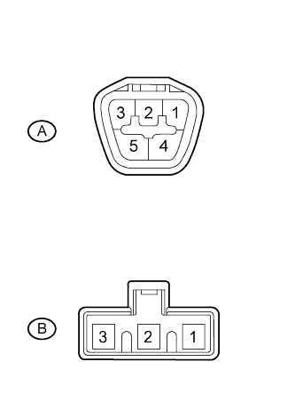
Measure the resistance according to the value(s) in the table below.
Standard Resistance Tester Connection Condition Specified Condition A-2 - B-2 Always Below 1 Ω A-3 - B-1 Result Result Proceed to OK A NG (w/ Canister Pump Module) B NG (w/o Canister Pump Module) C
B
REPLACE FUEL SUCTION PLATE SUB-ASSEMBLY Click here
C
REPLACE FUEL SUCTION PLATE SUB-ASSEMBLY Click here
A
-
-
INSPECT NO. 2 FUEL SENDER GAUGE ASSEMBLY
-
Remove the No. 2 fuel sender gauge assembly.
-
w/ Canister Pump Module Click here.
-
w/o Canister Pump Module Click here.
-
-
Inspect the No. 2 fuel sender gauge assembly.
-
w/ Canister Pump Module Click here.
-
w/o Canister Pump Module Click here.
Result Result Proceed to OK A NG (w/ Canister Pump Module) B NG (w/o Canister Pump Module) C
-
B
REPLACE NO. 2 FUEL SENDER GAUGE ASSEMBLY Click here
C
REPLACE NO. 2 FUEL SENDER GAUGE ASSEMBLY Click here
A
-
-
INSPECT FUEL TANK VENT TUBE ASSEMBLY
-
Remove the fuel tank vent tube assembly.
-
w/ Canister Pump Module Click here.
-
w/o Canister Pump Module Click here.
-
-
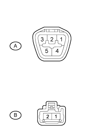
Measure the resistance according to the value(s) in the table below.
Standard Resistance Tester Connection Condition Specified Condition A-2 - B-2 Always Below 1 Ω A-3 - B-1 Result Result Proceed to OK A NG (w/ Canister Pump Module) B NG (w/o Canister Pump Module) C
B
REPLACE FUEL TANK VENT TUBE ASSEMBLY Click here
C
REPLACE FUEL TANK VENT TUBE ASSEMBLY Click here
A 
REPLACE COMBINATION METER ASSEMBLY Click here
-