METER / GAUGE SYSTEM, Diagnostic DTC:B1507, B1508

| DTC Code | DTC Name |
|---|---|
| B1507 | Open in Turn Signal Circuit |
| B1508 | Short in Turn Signal / Hazard Flasher Circuit |
DESCRIPTION
These DTCs are stored when the combination meter assembly detects an open in a turn signal light circuit, a short in a turn signal light circuit, or a short in the hazard warning light circuit.
| DTC Code | DTC Detection Condition | Trouble Area |
|---|---|---|
| B1507 | When IG voltage is 9.5 V or more and the following condition is detected:
|
|
| B1508 | When IG voltage is 9.5 V or more and the following condition is detected:
|
-
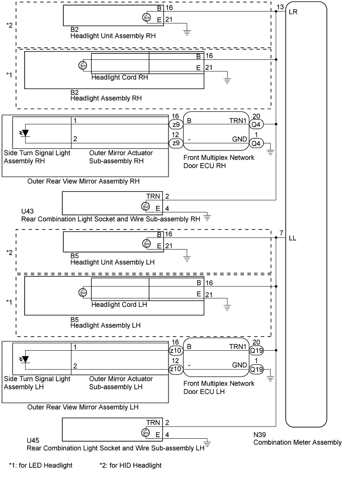
*1: for LED Headlight
-
*2: for HID Headlight
WIRING DIAGRAM
INSPECTION PROCEDURE
Note
Inspect the bulbs for circuits related to this system before performing the following inspection procedure.
PROCEDURE
-
CHECK FOR DTC
-
Clear the DTCs Click here.
-
Check for DTCs Click here.
OK DTC B1507 or B1508 output does not occur.
NG 
CONFIRM MALFUNCTIONING LIGHT Click here
OK 
USE SIMULATION METHOD TO CHECK Click here
-
-
CONFIRM MALFUNCTIONING LIGHT
-
Check the malfunctioning turn signal light.
Result Result Proceed to No right turn signal lights turn on A No left turn signal lights turn on B One of the right turn signal lights does not turn on C One of the left turn signal lights does not turn on D
B
CHECK HARNESS AND CONNECTOR (COMBINATION METER ASSEMBLY - FRONT MULTIPLEX NETWORK DOOR ECU LH) Click here
C
CONFIRM MALFUNCTIONING LIGHT (RH SIDE) Click here
D
CONFIRM MALFUNCTIONING LIGHT (LH SIDE) Click here
A 
-
-
CHECK HARNESS AND CONNECTOR (COMBINATION METER ASSEMBLY - FRONT MULTIPLEX NETWORK DOOR ECU RH)
-
Disconnect the N39 combination meter assembly connector.
-
Disconnect the Q4 front multiplex network door ECU RH connector.
-
Disconnect the B2 headlight unit assembly RH connector.
-
Disconnect the U43 rear combination light socket and wire sub-assembly RH connector.
-
Measure the resistance according to the value(s) in the table below.
Standard Resistance Tester Connection Condition Specified Condition N39-13 (LR) - Q4-20 (TRN1) Always Below 1 Ω N39-13 (LR) - Body ground Always 10 kΩ or higher
NG 
REPAIR OR REPLACE HARNESS OR CONNECTOR
OK
REPLACE COMBINATION METER ASSEMBLY Click here
-
-
CHECK HARNESS AND CONNECTOR (COMBINATION METER ASSEMBLY - FRONT MULTIPLEX NETWORK DOOR ECU LH)
-
Disconnect the N39 combination meter assembly connector.
-
Disconnect the Q19 front multiplex network door ECU LH connector.
-
Disconnect the B5 headlight unit assembly LH connector.
-
Disconnect the U45 rear combination light socket and wire sub-assembly LH connector.
-
Measure the resistance according to the value(s) in the table below.
Standard Resistance Tester Connection Condition Specified Condition N39-7 (LL) - Q19-20 (TRN1) Always Below 1 Ω N39-7 (LL) - Body ground Always 10 kΩ or higher
NG
REPAIR OR REPLACE HARNESS OR CONNECTOR
OK
REPLACE COMBINATION METER ASSEMBLY Click here
-
-
CONFIRM MALFUNCTIONING LIGHT (RH SIDE)
-
Check the malfunctioning turn signal light.
Result Result Proceed to Front turn signal light does not illuminate (for HID Headlight) A Front turn signal light does not illuminate (for LED Headlight) B Side turn signal light does not illuminate C Rear turn signal light does not illuminate D
B
CHECK HARNESS AND CONNECTOR (COMBINATION METER ASSEMBLY - HEADLIGHT ASSEMBLY RH AND BODY GROUND) Click here
C
CHECK HARNESS AND CONNECTOR (COMBINATION METER ASSEMBLY - FRONT MULTIPLEX NETWORK DOOR ECU RH AND BODY GROUND) Click here
D
CHECK HARNESS AND CONNECTOR (COMBINATION METER ASSEMBLY - REAR COMBINATION LIGHT SOCKET AND WIRE SUB-ASSEMBLY RH AND BODY GROUND) Click here
A
-
-
CHECK HARNESS AND CONNECTOR (COMBINATION METER ASSEMBLY - HEADLIGHT UNIT ASSEMBLY RH AND BODY GROUND)
-
Disconnect the N39 combination meter assembly connector.
-
Disconnect the B2 headlight unit assembly RH connector.
-
Disconnect the Q4 front multiplex network door ECU RH connector.
-
Disconnect the U43 rear combination light socket and wire sub-assembly RH connector.
-
Measure the resistance according to the value(s) in the table below.
Standard Resistance Tester Connection Condition Specified Condition N39-13 (LR) - B2-16 (B) Always Below 1 Ω B2-21 (E) - Body ground N39-13 (LR) - Body ground Always 10 kΩ or higher
NG
REPAIR OR REPLACE HARNESS OR CONNECTOR
OK
REPLACE HEADLIGHT UNIT ASSEMBLY RH Click here
-
-
CHECK HARNESS AND CONNECTOR (COMBINATION METER ASSEMBLY - HEADLIGHT ASSEMBLY RH AND BODY GROUND)
-
Disconnect the N39 combination meter assembly connector.
-
Disconnect the B2 headlight assembly RH connector.
-
Disconnect the Q4 front multiplex network door ECU RH connector.
-
Disconnect the U43 rear combination light socket and wire sub-assembly RH connector.
-
Measure the resistance according to the value(s) in the table below.
Standard Resistance Tester Connection Condition Specified Condition N39-13 (LR) - B2-16 (B) Always Below 1 Ω B2-21 (E) - Body ground N39-13 (LR) - Body ground Always 10 kΩ or higher
NG
REPAIR OR REPLACE HARNESS OR CONNECTOR
OK
-
-
CHECK HEADLIGHT CORD RH
-
Replace the headlight cord RH with a new or normally functioning one Click here.
-
Check for DTCs Click here.
OK DTC B1507 or B1508 output does not occur.
NG
REPLACE HEADLIGHT ASSEMBLY RH Click here
OK
END (HEADLIGHT CORD RH WAS DEFECTIVE)
-
-
CHECK HARNESS AND CONNECTOR (COMBINATION METER ASSEMBLY - FRONT MULTIPLEX NETWORK DOOR ECU RH AND BODY GROUND)
-
Disconnect the N39 combination meter assembly connector.
-
Disconnect the Q4 front multiplex network door ECU RH connector.
-
Disconnect the B2 headlight unit assembly RH connector.
-
Disconnect the U43 rear combination light socket and wire sub-assembly RH connector.
-
Measure the resistance according to the value(s) in the table below.
Standard Resistance Tester Connection Condition Specified Condition N39-13 (LR) - Q4-20 (TRN1) Always Below 1 Ω Q4-1 (GND) - Body ground N39-13 (LR) - Body ground Always 10 kΩ or higher
NG
REPAIR OR REPLACE HARNESS OR CONNECTOR
OK
-
-
INSPECT OUTER REAR VIEW MIRROR ASSEMBLY RH
-
Remove the outer rear view mirror assembly RH Click here.
-
Connect the positive (+) lead from the battery to terminal 16 and the negative (-) lead to terminal 12, and check that the light comes on.
OK Light comes on.
NG
INSPECT SIDE TURN SIGNAL LIGHT ASSEMBLY RH Click here
OK
REPLACE FRONT MULTIPLEX NETWORK DOOR ECU RH Click here
-
-
INSPECT SIDE TURN SIGNAL LIGHT ASSEMBLY RH
-
Remove the side turn signal light assembly RH Click here.
-
Inspect the side turn signal light assembly RH Click here.
NG
REPLACE SIDE TURN SIGNAL LIGHT ASSEMBLY RH Click here
OK
REPLACE OUTER MIRROR ACTUATOR SUB-ASSEMBLY RH Click here
-
-
CHECK HARNESS AND CONNECTOR (COMBINATION METER ASSEMBLY - REAR COMBINATION LIGHT SOCKET AND WIRE SUB-ASSEMBLY RH AND BODY GROUND)
-
Disconnect the N39 combination meter assembly connector.
-
Disconnect the U43 rear combination light socket and wire sub-assembly RH connector.
-
Disconnect the B2 headlight unit assembly RH connector.
-
Disconnect the Q4 front multiplex network door ECU RH connector.
-
Measure the resistance according to the value(s) in the table below.
Standard Resistance Tester Connection Condition Specified Condition N39-13 (LR) - U43-2 (TRN) Always Below 1 Ω U43-4 (E) - Body ground N39-13 (LR) - Body ground Always 10 kΩ or higher
NG
REPAIR OR REPLACE HARNESS OR CONNECTOR
OK
REPLACE REAR COMBINATION LIGHT SOCKET AND WIRE SUB-ASSEMBLY RH Click here
-
-
CONFIRM MALFUNCTIONING LIGHT (LH SIDE)
-
Check the malfunctioning turn signal light.
Result Result Proceed to Front turn signal light does not illuminate (for HID Headlight) A Front turn signal light does not illuminate (for LED Headlight) B Side turn signal light does not illuminate C Rear turn signal light does not illuminate D
B
CHECK HARNESS AND CONNECTOR (COMBINATION METER ASSEMBLY - HEADLIGHT ASSEMBLY LH AND BODY GROUND) Click here
C
CHECK HARNESS AND CONNECTOR (COMBINATION METER ASSEMBLY - FRONT MULTIPLEX NETWORK DOOR ECU LH AND BODY GROUND) Click here
D
CHECK HARNESS AND CONNECTOR (COMBINATION METER ASSEMBLY - REAR COMBINATION LIGHT SOCKET AND WIRE SUB-ASSEMBLY LH AND BODY GROUND) Click here
A
-
-
CHECK HARNESS AND CONNECTOR (COMBINATION METER ASSEMBLY - HEADLIGHT UNIT ASSEMBLY LH AND BODY GROUND)
-
Disconnect the N39 combination meter assembly connector.
-
Disconnect the B5 headlight unit assembly LH connector.
-
Disconnect the Q19 front multiplex network door ECU LH connector.
-
Disconnect the U45 rear combination light socket and wire sub-assembly LH connector.
-
Measure the resistance according to the value(s) in the table below.
Standard Resistance Tester Connection Condition Specified Condition N39-7 (LL) - B5-16 (B) Always Below 1 Ω B5-21 (E) - Body ground N39-7 (LL) - Body ground Always 10 kΩ or higher
NG
REPAIR OR REPLACE HARNESS OR CONNECTOR
OK
REPLACE HEADLIGHT UNIT ASSEMBLY LH Click here
-
-
CHECK HARNESS AND CONNECTOR (COMBINATION METER ASSEMBLY - HEADLIGHT ASSEMBLY LH AND BODY GROUND)
-
Disconnect the N39 combination meter assembly connector.
-
Disconnect the B5 headlight assembly LH connector.
-
Disconnect the Q19 front multiplex network door ECU LH connector.
-
Disconnect the U45 rear combination light socket and wire sub-assembly LH connector.
-
Measure the resistance according to the value(s) in the table below.
Standard Resistance Tester Connection Condition Specified Condition N39-7 (LL) - B5-16 (B) Always Below 1 Ω B5-21 (E) - Body ground N39-7 (LL) - Body ground Always 10 kΩ or higher
NG
REPAIR OR REPLACE HARNESS OR CONNECTOR
OK
-
-
CHECK HEADLIGHT CORD LH
-
Replace the headlight cord RH with a new or normally functioning one Click here.
-
Check for DTCs Click here.
OK DTC B1507 or B1508 output does not occur.
NG
REPLACE HEADLIGHT ASSEMBLY LH Click here
OK
END (HEADLIGHT CORD LH WAS DEFECTIVE)
-
-
CHECK HARNESS AND CONNECTOR (COMBINATION METER ASSEMBLY - FRONT MULTIPLEX NETWORK DOOR ECU LH AND BODY GROUND)
-
Disconnect the N39 combination meter assembly connector.
-
Disconnect the Q19 front multiplex network door ECU LH connector.
-
Disconnect the B5 headlight unit assembly LH connector.
-
Disconnect the U45 rear combination light socket and wire sub-assembly LH connector.
-
Measure the resistance according to the value(s) in the table below.
Standard Resistance Tester Connection Condition Specified Condition N39-7 (LL) - Q19-20 (TRN1) Always Below 1 Ω Q19-1 (GND) - Body ground N39-7 (LL) - Body ground Always 10 kΩ or higher
NG
REPAIR OR REPLACE HARNESS OR CONNECTOR
OK
-
-
INSPECT OUTER REAR VIEW MIRROR ASSEMBLY LH
-
Remove the outer rear view mirror assembly LH Click here.
-
Connect the positive (+) lead from the battery to terminal 16 and the negative (-) lead to terminal 12, and check that the light comes on.
OK Light comes on.
NG
INSPECT SIDE TURN SIGNAL LIGHT ASSEMBLY LH Click here
OK
REPLACE FRONT MULTIPLEX NETWORK DOOR ECU LH Click here
-
-
INSPECT SIDE TURN SIGNAL LIGHT ASSEMBLY LH
-
Remove the side turn signal light assembly LH Click here.
-
Inspect the side turn signal light assembly LH Click here.
NG
REPLACE SIDE TURN SIGNAL LIGHT ASSEMBLY LH Click here
OK
REPLACE OUTER MIRROR ACTUATOR SUB-ASSEMBLY LH Click here
-
-
CHECK HARNESS AND CONNECTOR (COMBINATION METER ASSEMBLY - REAR COMBINATION LIGHT SOCKET AND WIRE SUB-ASSEMBLY LH AND BODY GROUND)
-
Disconnect the N39 combination meter assembly connector.
-
Disconnect the U45 rear combination light socket and wire sub-assembly LH connector.
-
Disconnect the B5 headlight unit assembly LH connector.
-
Disconnect the Q19 front multiplex network door ECU LH connector.
-
Measure the resistance according to the value(s) in the table below.
Standard Resistance Tester Connection Condition Specified Condition N39-7 (LL) - U45-2 (TRN) Always Below 1 Ω U45-4 (E) - Body ground N39-7 (LL) - Body ground Always 10 kΩ or higher
NG
REPAIR OR REPLACE HARNESS OR CONNECTOR
OK
REPLACE REAR COMBINATION LIGHT SOCKET AND WIRE SUB-ASSEMBLY LH Click here
-