METER / GAUGE SYSTEM Operating Light Control Rheostat does not Change Light Brightness
DESCRIPTION
The meter CPU receives signals from this circuit to adjust the illumination of the meter. The meter CPU sets the illumination level based on the user operation of the light control rheostat up or down switches.
Tech Tips
-
The meter illumination level can be adjusted by pressing the light control rheostat up or down switches.
-
The meter illumination dims when the light control switch is turned to the tail or head position at night.
-
Setting the meter illumination to maximum brightness cancels the above dimming of the meter illumination.
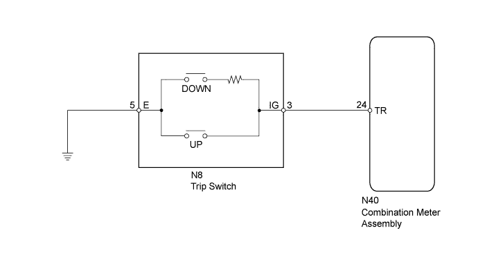
WIRING DIAGRAM
INSPECTION PROCEDURE
PROCEDURE
-
READ VALUE USING GTS (RHEOSTAT SWITCH)
-
Use the Data List to check the rheostat switch Click here.
Combination Meter Tester Display Measurement Item/Range Normal Condition Diagnostic Note Light Control Up Switch Light control rheostat up switch/OFF or ON OFF: Light control rheostat up switch not pressed - ON: Light control rheostat up switch pressed Light Control Down Switch Light control rheostat down switch/ OFF or ON OFF: Light control rheostat down switch not pressed - ON: Light control rheostat down switch pressed OK The value displayed on the GTS changes in accordance with the actual rheostat switch operation.
NG 
INSPECT TRIP SWITCH Click here
OK 
REPLACE COMBINATION METER ASSEMBLY Click here
-
-
INSPECT TRIP SWITCH
-
Remove the trip switch Click here.
-
Inspect the trip switch Click here.
NG 
REPLACE TRIP SWITCH Click here
OK 
-
-
CHECK HARNESS AND CONNECTOR (COMBINATION METER ASSEMBLY - TRIP SWITCH AND BODY GROUND)
-
Disconnect the N40 combination meter assembly connector.
-
Disconnect the N8 trip switch connector.
-
Measure the resistance according to the value(s) in the table below.
Standard Resistance Tester Connection Condition Specified Condition N40-24 (TR) - N8-3 (IG) Always Below 1 Ω N8-5 (E) - Body ground N40-24 (TR) - Body ground Always Below 1 Ω
NG
REPAIR OR REPLACE HARNESS OR CONNECTOR
OK
REPLACE COMBINATION METER ASSEMBLY Click here
-