LIGHTING SYSTEM Door Mirror Foot Light Circuit
DESCRIPTION
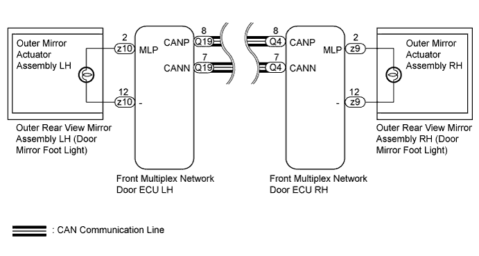
The front multiplex network door ECU controls the door mirror foot lights.
WIRING DIAGRAM
INSPECTION PROCEDURE
Note
-
First perform the communication function inspections in How to Proceed with Troubleshooting to confirm that there are no CAN communication malfunctions before troubleshooting this symptom.
-
Inspect the bulbs for circuits related to this system before performing the following inspection procedure.
PROCEDURE
-
PERFORM ACTIVE TEST USING GTS (DOOR MIRROR FOOT LIGHT)
-
Using the GTS, perform the Active Test Click here.
Front Left Door Tester Display Test Part Control Range Diagnostic Note Foot Light Door mirror foot light LH ON/OFF - Front Right Door Tester Display Test Part Control Range Diagnostic Note Foot Light Door mirror foot light RH ON/OFF - OK Door mirror foot light illuminates. Result Result Proceed to OK A NG (Outer rear view mirror RH [door mirror foot light] does not illuminate) B NG (Outer rear view mirror LH [door mirror foot light] does not illuminate) C
B 
INSPECT OUTER REAR VIEW MIRROR RH Click here
C
INSPECT OUTER REAR VIEW MIRROR LH Click here
A 
PROCEED TO NEXT SUSPECTED AREA SHOWN IN PROBLEM SYMPTOMS TABLE Click here
-
-
INSPECT OUTER REAR VIEW MIRROR RH
-
Remove the outer rear view mirror RH (door mirror foot light) Click here.
-
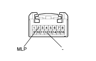
Connect a positive (+) lead from the battery to terminal 2 (MLP) and a negative (-) lead to terminal 12 (-).
-
Check that the door mirror foot light illuminates.
OK Door mirror foot light illuminates.
NG 
REPLACE OUTER MIRROR ACTUATOR ASSEMBLY RH Click here
OK
REPLACE FRONT MULTIPLEX NETWORK DOOR ECU RH Click here
-
-
INSPECT OUTER REAR VIEW MIRROR LH
-
Remove the outer rear view mirror LH (door mirror foot light) Click here.
-
Connect a positive (+) lead from the battery to terminal 2 (MLP) and a negative (-) lead to terminal 12 (-).
-
Check that the door mirror foot light illuminates.
OK Door mirror foot light illuminates.
NG
REPLACE OUTER MIRROR ACTUATOR ASSEMBLY LH Click here
OK
REPLACE FRONT MULTIPLEX NETWORK DOOR ECU LH Click here
-