LIGHTING SYSTEM Interior Light Circuit
DESCRIPTION
The main body ECU controls the map light and spot light.
WIRING DIAGRAM
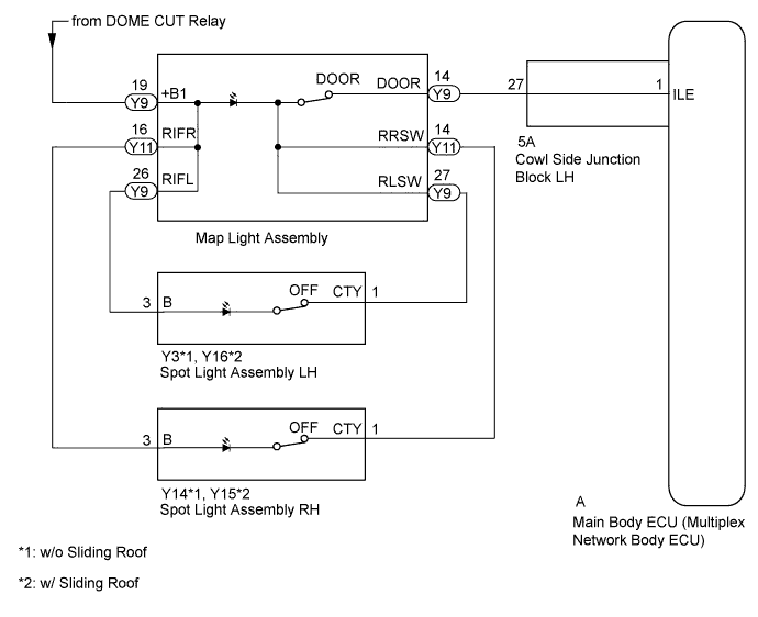
INSPECTION PROCEDURE
Note
-
Recognition code registration is necessary when replacing the main body ECU (multiplex network body ECU).
-
If the main body ECU (multiplex network body ECU) is replaced, refer to the Service Bulletin.
PROCEDURE
-
PERFORM ACTIVE TEST USING GTS (MAP LIGHT, SPOT LIGHT)
-
Using the GTS, perform the Active Test Click here.
Main Body Tester Display Test Part Control Range Diagnostic Note Illuminated Entry System Map light and spot light ON/OFF - OK Map light and spot light comes on.
NG 
INSPECT MAP LIGHT Click here
OK 
PROCEED TO NEXT SUSPECTED AREA SHOWN IN PROBLEM SYMPTOMS TABLE Click here
-
-
INSPECT MAP LIGHT
-
Remove the map light Click here.
-
Turn the door position switch to door mode.
-
Connect the positive (+) lead from the battery to terminal Y9-19 (+B1) and the negative (-) lead to terminal Y9-14 (DOOR), then check that the map light (dome light portion) illuminates.
OK Map light (dome light portion) illuminates -
Measure the resistance according to the value(s) in the table below.
Standard Resistance Tester Connection Condition Specified Condition Y9-19 (+B1) - Y11-16 (RIFR) Always Below 1 Ω Y9-19 (+B1) - Y9-26 (RIFL) Y9-27 (RLSW) - Y9-14 (DOOR) Turn the door position switch to door mode Below 1 Ω Turn the door position switch off mode 10 kΩ or higher Y11-14 (RRSW) - Y9-14 (DOOR) Turn the door position switch to door mode Below 1 Ω Turn the door position switch off mode 10 kΩ or higher
NG 
REPLACE MAP LIGHT ASSEMBLY Click here
OK 
-
-
INSPECT SPOT LIGHT ASSEMBLY LH
-
Remove the spot light LH Click here.
-
Inspect the spot light LH Click here.
NG
REPLACE SPOT LIGHT ASSEMBLY LH Click here
OK
-
-
INSPECT SPOT LIGHT ASSEMBLY RH
-
Remove the spot light RH Click here.
-
Inspect the spot light RH Click here.
NG
REPLACE SPOT LIGHT ASSEMBLY RH Click here
OK
-
-
CHECK HARNESS AND CONNECTOR (MAP LIGHT - SPOT LIGHT LH)
-
Disconnect the Y9 map light connector.
-
Disconnect the Y3*1 or Y16*2 spot light LH connector.
-
*1: w/o Sliding Roof
-
*2: w/ Sliding Roof
-
-
Measure the resistance according to the value(s) in the table below.
Standard Resistance w/o Sliding Roof Tester Connection Condition Specified Condition Y9-26 (RIFL) - Y3-3 (B) Always Below 1 Ω Y9-26 (RIFL) - Body ground 10 kΩ or higher Y9-27 (RLSW) - Y3-1 (CTY) Always Below 1 Ω Y9-27 (RLSW) - Body ground 10 kΩ or higher w/ Sliding Roof Tester Connection Condition Specified Condition Y9-26 (RIFL) - Y16-3 (B) Always Below 1 Ω Y9-26 (RIFL) - Body ground 10 kΩ or higher Y9-27 (RLSW) - Y16-1 (CTY) Always Below 1 Ω Y9-27 (RLSW) - Body ground 10 kΩ or higher
NG
REPAIR OR REPLACE HARNESS OR CONNECTOR
OK
-
-
CHECK HARNESS AND CONNECTOR (MAP LIGHT - SPOT LIGHT RH)
-
Disconnect the Y11 map light connector.
-
Disconnect the Y14*1 or Y15*2 spot light RH connector.
-
*1: w/o Sliding Roof
-
*2: w/ Sliding Roof
-
-
Measure the resistance according to the value(s) in the table below.
Standard Resistance w/o Sliding Roof Tester Connection Condition Specified Condition Y11-16 (RIFR) - Y14-3 (B) Always Below 1 Ω Y11-16 (RIFR) - Body ground 10 kΩ or higher Y11-14 (RRSW) - Y14-1 (CTY) Always Below 1 Ω Y11-14 (RRSW) - Body ground 10 kΩ or higher w/ Sliding Roof Tester Connection Condition Specified Condition Y11-16 (RIFR) - Y15-3 (B) Always Below 1 Ω Y11-16 (RIFR) - Body ground 10 kΩ or higher Y11-14 (RRSW) - Y15-1 (CTY) Always Below 1 Ω Y11-14 (RRSW) - Body ground 10 kΩ or higher
NG
REPAIR OR REPLACE HARNESS OR CONNECTOR
OK
-
-
CHECK HARNESS AND CONNECTOR (MAP LIGHT - COWL SIDE JUNCTION BLOCK LH AND BATTERY)
-
Disconnect the Y9 map light connector.
-
Disconnect the 5A cowl side junction block LH connector.
-
Measure the voltage according to the value(s) in the table below.
Standard Voltage Tester Connection Condition Specified Condition Y9-19 (+B1) - Y11-16 (RIFR) Battery saving control not operating 11 to 14 V -
Measure the resistance according to the value(s) in the table below.
Standard Resistance Tester Connection Condition Specified Condition Y9-14 (DOOR) - 5A-27 Always Below 1 Ω Y9-14 (DOOR) - Body ground 10 kΩ or higher
NG
REPAIR OR REPLACE HARNESS OR CONNECTOR
OK
-
-
INSPECT COWL SIDE JUNCTION BLOCK LH
-
Remove the cowl side junction block LH Click here.
-
Remove the main body ECU from the cowl side junction block LH Click here.
-
Measure the resistance according to the value(s) in the table below.
Standard Resistance Tester Connection Condition Specified Condition A-1 (ILE) - 5A-27 Always Below 1 Ω
NG
REPLACE COWL SIDE JUNCTION BLOCK LH Click here
OK
REPLACE MAIN BODY ECU (MULTIPLEX NETWORK BODY ECU) Click here
-