| Power switch
|
-
Turns on the power and starts the hybrid control system.
-
Contains a built-in transponder key amplifier to start the hybrid control system when the key does not operate properly due to a depleted auxiliary battery or wave interference.
|
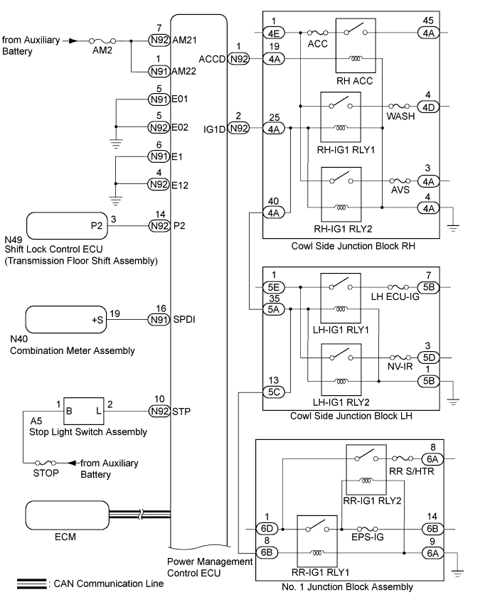
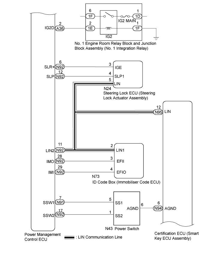
| Power management control ECU |
-
Changes the power source mode in 4 stages (off, on (ACC), on (IG), on (READY)) in accordance with the shift state and stop light switch.
-
Controls the push-button start function in accordance with signals received from switches and ECUs.
-
The power management control ECU and certification ECU (smart key ECU assembly) permit starting of the hybrid control system after receiving an unlock signal from the steering lock actuator assembly (steering lock ECU).
|
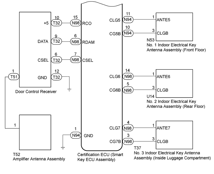
| Certification ECU (smart key ECU assembly) |
-
Performs key verification.
-
Controls the electrical key antenna (indoor).
-
Outputs immobiliser set/unset commands.
-
Outputs steering lock actuator assembly lock/unlock command signals.
-
Forms the vehicle interior function detection area.
|
| ID code box (immobiliser code ECU) |
-
Receives command signals from the certification ECU (smart key ECU) and outputs immobiliser set and unset command signals to the power management control ECU.
-
Records codes for push-button start verification.
|
| Steering lock ECU (steering lock actuator assembly) |
|
| Combination meter assembly |
-
Operates various warnings (messages on the multi-information display, sounding of the buzzer in the combination meter, blinking or illumination of the entry warning light) according to the command signals from the certification ECU (smart key ECU).
-
Outputs a vehicle speed signal to the ECUs.
|
| IG, ACC relay |
Turns on/off according to the power management control ECU and provides power to each system. |
| Stop light switch assembly |
Detects that the brake pedal has been depressed (switch is on) and outputs a signal to the power management control ECU. |
| No. 1 indoor electrical key antenna assembly (front floor) No. 2 indoor electrical key antenna assembly (rear floor) No. 3 indoor electrical key antenna assembly (inside luggage compartment) |
Sends the request code from the certification ECU (smart key ECU) and forms the vehicle interior detection area. |
| Door control receiver |
Receives the push-button start code/wireless code sent from the key and sends it to the certification ECU (smart key ECU). |
| Electrical key transmitter sub-assembly |
Sends the ID code upon receiving a request signal. |