POWER DOOR LOCK CONTROL SYSTEM All Doors LOCK/UNLOCK Functions do not Operate Via Door Control Switch
DESCRIPTION
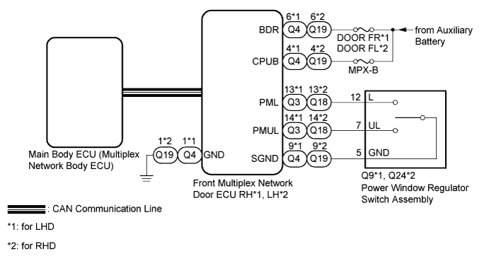
The main body ECU (multiplex network body ECU) receives switch signals from the power window regulator switch assembly (door control switch) on the front passenger door and activates the door lock motor on each door according to these signals.
WIRING DIAGRAM
INSPECTION PROCEDURE
Note
-
When using the GTS with the power switch off to troubleshoot:
Connect the GTS to the DLC3 and turn a courtesy light switch on and off at 1.5-seconds intervals until communication between the GTS and vehicle begins.
-
Inspect the fuses for circuits related to this system before performing the following inspection procedure.
Tech Tips
Since the power door lock control system has functions that use LIN communication system and CAN communication system, first confirm that there is no malfunction in the communication system by inspecting the LIN communication and CAN communication functions in accordance with the "How to Proceed with Troubleshooting" procedures. Then, conduct the following inspection procedure.
PROCEDURE
-
READ VALUE USING GTS (DOOR CONTROL SWITCH)
-
Use the Data List to check if the door control switch is functioning properly Click here.
Front Right Door (for LHD) Tester Display Measurement Item/Range Normal Condition Diagnostic Note Door Lock SW Power window regulator switch assembly (door control switch) lock signal/ON or OFF ON: Lock side of power window regulator switch assembly pushed
OFF: Lock side of power window regulator switch assembly not pushed
- Door Unlock SW Power window regulator switch assembly (door control switch) unlock signal/ON or OFF ON: Unlock side of power window regulator switch assembly pushed
OFF: Unlock side of power window regulator switch assembly not pushed
- Front Left Door (for RHD) Tester Display Measurement Item/Range Normal Condition Diagnostic Note Door Lock SW Power window regulator switch assembly (door control switch) lock signal/ON or OFF ON: Lock side of power window regulator switch assembly pushed
OFF: Lock side of power window regulator switch assembly not pushed
- Door Unlock SW Power window regulator switch assembly (door control switch) unlock signal/ON or OFF ON: Unlock side of power window regulator switch assembly pushed
OFF: Unlock side of power window regulator switch assembly not pushed
- OK The GTS indicates ON or OFF according to the switch operation shown in the table.
NG 
INSPECT POWER WINDOW REGULATOR SWITCH ASSEMBLY Click here
OK 
REPLACE FRONT MULTIPLEX NETWORK DOOR ECU (for Front Passenger Side) Click here
-
-
INSPECT POWER WINDOW REGULATOR SWITCH ASSEMBLY
-
Remove the power window regulator switch assembly (door control switch) Click here.
-
Inspect the power window regulator switch assembly (door control switch) Click here.
NG 
REPLACE POWER WINDOW REGULATOR SWITCH ASSEMBLY Click here
OK 
-
-
CHECK HARNESS AND CONNECTOR (FRONT MULTIPLEX NETWORK DOOR ECU - POWER WINDOW REGULATOR SWITCH ASSEMBLY)
-
*1: for LHD
-
*2: for RHD
-
Disconnect the Q3 and Q4*1 or Q18 or Q19*2 front multiplex network door ECU (for Front Passenger Side) connectors.
-
Disconnect the Q9*1 or Q24*2 power window regulator switch assembly (door control switch) connector.
-
Measure the resistance according to the value(s) in the table below.
Standard Resistance for LHD Tester Connection Condition Specified Condition Q3-13 (PML) - Q9-12 (L) Always Below 1 Ω Q3-14 (PMUL) - Q9-7 (UL) Always Below 1 Ω Q4-9 (SGND) - Q9-5 (GND) Always Below 1 Ω Q3-13 (PML) or Q9-12 (L) - Body ground Always 10 kΩ or higher Q3-14 (PMUL) or Q9-7 (UL) - Body ground Always 10 kΩ or higher Q4-9 (SGND) or Q9-5 (GND) - Body ground Always 10 kΩ or higher for RHD Tester Connection Condition Specified Condition Q18-13 (PML) - Q24-12 (L) Always Below 1 Ω Q18-14 (PMUL) - Q24-7 (UL) Always Below 1 Ω Q19-9 (SGND) - Q24-5 (GND) Always Below 1 Ω Q18-13 (PML) or Q24-12 (L) - Body ground Always 10 kΩ or higher Q18-14 (PMUL) or Q24-7 (UL) - Body ground Always 10 kΩ or higher Q19-9 (SGND) or Q24-5 (GND) - Body ground Always 10 kΩ or higher
NG
REPAIR OR REPLACE HARNESS OR CONNECTOR
OK
-
-
CHECK HARNESS AND CONNECTOR (FRONT MULTIPLEX NETWORK DOOR ECU - BATTERY AND BODY GROUND)
-
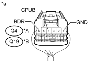
Text in Illustration *A for LHD *B for RHD *a Rear view of wire harness connector
(to Front Multiplex Network Door ECU [for Front Passenger Side])
Disconnect the front multiplex network door ECU (for Front Passenger Side) connector.
-
Measure the resistance according to the value(s) in the table below.
Standard Resistance for LHD Tester Connection Condition Specified Condition Q4-1 (GND) - Body ground Always Below 1 Ω for RHD Tester Connection Condition Specified Condition Q19-1 (GND) - Body ground Always Below 1 Ω -
Measure the voltage according to the value(s) in the table below.
Standard Voltage for LHD Tester Connection Condition Specified Condition Q4-4 (CPUB) - Body ground Always 11 to 14 V Q4-6 (BDR) - Body ground Always 11 to 14 V for RHD Tester Connection Condition Specified Condition Q19-4 (CPUB) - Body ground Always 11 to 14 V Q19-6 (BDR) - Body ground Always 11 to 14 V
NG
REPAIR OR REPLACE HARNESS OR CONNECTOR
OK
REPLACE FRONT MULTIPLEX NETWORK DOOR ECU (for Front Passenger Side) Click here
-