POWER DOOR LOCK CONTROL SYSTEM, Diagnostic DTC:B1243

| DTC Code | DTC Name |
|---|---|
| B1243 | GSW Terminal Circuit Malfunction |
DESCRIPTION
If the collision door lock release function does not operate normally, or an open or short in the GSW input circuit of the main body ECU (multiplex network body ECU) is detected, DTC B1243 will be stored.
Tech Tips
If DTC B1243 is stored, the speed-sensitive automatic door lock function, shift-linked automatic door lock function, and collision door lock release function will be prohibited.
| DTC Code | DTC Detection Condition | Trouble Area |
|---|---|---|
| B1243 | A malfunction occurs in the GSW input circuit of the main body ECU (multiplex network body ECU). |
|
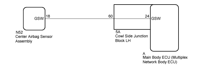
WIRING DIAGRAM
INSPECTION PROCEDURE
Note
-
After turning the power switch off, waiting time may be required before disconnecting the cable from the auxiliary battery terminal. Therefore, make sure to read the disconnecting the cable from the auxiliary battery terminal notice before proceeding with work Click here.
-
When disconnecting the cable from the negative (-) auxiliary battery terminal while performing repairs, some systems need to be initialized after the cable is reconnected Click here.
-
When using the GTS with the power switch off to troubleshoot:
Connect the GTS to the DLC3 and turn a courtesy light switch on and off at 1.5-seconds intervals until communication between the GTS and vehicle begins.
-
If the main body ECU (multiplex network body ECU) is replaced, refer to Service Bulletin.
PROCEDURE
-
CLEAR DTC
-
Clear the DTCs Click here.
NEXT 
-
-
CHECK FOR DTC
-
Check for DTCs Click here.
OK DTC B1243 is not output.
NG 
CHECK HARNESS AND CONNECTOR (MAIN BODY ECU [MULTIPLEX NETWORK BODY ECU] - CENTER AIRBAG SENSOR ASSEMBLY) Click here
OK 
USE SIMULATION METHOD TO CHECK Click here
-
-
CHECK HARNESS AND CONNECTOR (MAIN BODY ECU [MULTIPLEX NETWORK BODY ECU] - CENTER AIRBAG SENSOR ASSEMBLY)
-
Disconnect the cable from the negative (-) auxiliary battery terminal, and wait for at least 90 seconds.
-
Remove the main body ECU (multiplex network body ECU) Click here.
-
Disconnect the N52 center airbag sensor assembly connector Click here.
-
Measure the resistance according to the value(s) in the table below.
Standard Resistance Tester Connection Condition Specified Condition A-24 - N52-18 (GSW) Always Below 1 Ω A-24 or N52-18 (GSW) - Body ground Always 10 kΩ or higher
NG
CHECK HARNESS AND CONNECTOR (COWL SIDE JUNCTION BLOCK LH - CENTER AIRBAG SENSOR ASSEMBLY) Click here
OK
-
-
CHECK MAIN BODY ECU (MULTIPLEX NETWORK BODY ECU) (GSW VOLTAGE)
-
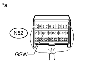
Text in Illustration *a Rear view of wire harness connector
(to Center Airbag Sensor Assembly)
Disconnect the cable from the negative (-) auxiliary battery terminal, and wait for at least 90 seconds.
-
Disconnect the center airbag sensor assembly connector Click here.
-
Connect the cable to the negative (-) auxiliary battery terminal, and wait for at least 2 seconds.
-
Turn the power switch on (IG).
-
Measure the voltage according to the value(s) in the table below.
Standard Voltage Tester Connection Switch Condition Specified Condition N52-18 (GSW) - Body ground Power switch on (IG) 4.5 to 5.5 V
NG 
REPLACE CENTER AIRBAG SENSOR ASSEMBLY Click here
OK
REPLACE MAIN BODY ECU (MULTIPLEX NETWORK BODY ECU) Click here
-
-
CHECK HARNESS AND CONNECTOR (COWL SIDE JUNCTION BLOCK LH - CENTER AIRBAG SENSOR ASSEMBLY)
-
Disconnect the cable from the negative (-) auxiliary battery terminal, and wait for at least 90 seconds.
-
Disconnect the 5A cowl side junction block LH connector.
-
Disconnect the N52 center airbag sensor assembly connector Click here.
-
Measure the resistance according to the value(s) in the table below.
Standard Resistance Tester Connection Condition Specified Condition 5A-60 - N52-18 (GSW) Always Below 1 Ω 5A-60 or N52-18 (GSW) - Body ground Always 10 kΩ or higher
NG
REPAIR OR REPLACE HARNESS OR CONNECTOR
OK
REPLACE COWL SIDE JUNCTION BLOCK LH Click here
-