LIN COMMUNICATION SYSTEM, Diagnostic DTC:B278C

| DTC Code | DTC Name |
|---|---|
| B278C | Lost Communication with Power Source Control |
DESCRIPTION
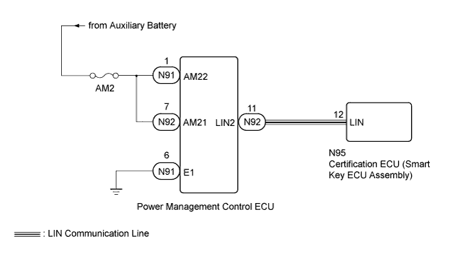
This DTC is stored when LIN communication between the certification ECU (smart key ECU assembly) and power management control ECU stops for 10 seconds or more.
| DTC Code | DTC Detection Condition | Trouble Area |
|---|---|---|
| B278C | No communication between the certification ECU (smart key ECU assembly) and power management control ECU for 10 seconds or more. |
|
WIRING DIAGRAM
INSPECTION PROCEDURE
Note
-
When using the GTS with the power switch off to troubleshoot:
Connect the GTS to the vehicle, and turn a courtesy switch on and off at 1.5 seconds intervals until communication between the GTS and vehicle begins.
-
Inspect the fuses for circuits related to this system before performing the following inspection procedure.
-
Before replacing the certification ECU (smart key ECU assembly), refer to the entry and start system (for Entry Function) Click here.
PROCEDURE
-
CLEAR DTC
-
Clear the DTCs Click here.
NEXT 
-
-
CHECK FOR DTC
-
Check for DTCs Click here.
Result Result Proceed to DTC B278C is output A DTC B278C is not output B
B 
USE SIMULATION METHOD TO CHECK Click here
A
-
-
CHECK HARNESS AND CONNECTOR (CERTIFICATION ECU [SMART KEY ECU] - POWER MANAGEMENT CONTROL ECU)
-
Disconnect the N95 certification ECU (smart key ECU assembly) connector.
-
Disconnect the N92 power management control ECU connector.
Standard Resistance Tester Connection Condition Specified Condition N95-12 (LIN) - N92-11 (LIN2) Always Below 1 Ω N95-12 (LIN) - Body ground Always 10 kΩ or higher
NG
REPAIR OR REPLACE HARNESS OR CONNECTOR
OK
-
-
CHECK HARNESS AND CONNECTOR (POWER MANAGEMENT CONTROL ECU - BATTERY AND BODY GROUND)
-
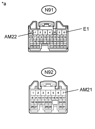
Text in Illustration *a Front view of wire harness connector
(to Power Management Control ECU)
Disconnect the power management control ECU connectors.
-
Measure the voltage according to the value(s) in the table below.
Standard Voltage Tester Connection Condition Specified Condition N91-1 (AM22) - Body ground Always 11 to 14 V N92-7 (AM21) - Body ground Always 11 to 14 V -
Measure the resistance according to the value(s) in the table below.
Standard Resistance Tester Connection Condition Specified Condition N91-6 (E1) - Body ground Always Below 1 Ω
NG
REPAIR OR REPLACE HARNESS OR CONNECTOR
OK
-
-
REPLACE POWER MANAGEMENT CONTROL ECU
-
Replace the power management control ECU with a new or normally functioning one Click here.
NEXT
-
-
CLEAR DTC
-
Clear the DTCs Click here.
NEXT
-
-
CHECK FOR DTC
-
Check for DTCs Click here.
OK DTC B278C is not output.
NG
REPLACE CERTIFICATION ECU (SMART KEY ECU ASSEMBLY)
OK 
END (POWER MANAGEMENT CONTROL ECU IS DEFECTIVE)
-