LIN COMMUNICATION SYSTEM, Diagnostic DTC:B2786

| DTC Code | DTC Name |
|---|---|
| B2786 | No Response from Steering Lock ECU |
DESCRIPTION
This DTC is output when LIN communication between the certification ECU (smart key ECU assembly) and steering lock actuator assembly stops for 10 seconds or more.
| DTC Code | DTC Detection Condition | Trouble Area |
|---|---|---|
| B2786 | Periodic transmission from steering lock actuator assembly stops for 10 seconds or more |
|
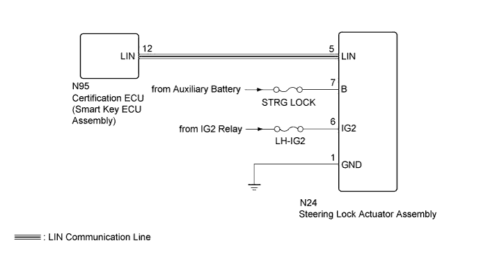
WIRING DIAGRAM
INSPECTION PROCEDURE
Note
-
When using the GTS with the power switch off to troubleshoot:
Connect the GTS to the vehicle, and turn a courtesy switch on and off at 1.5 seconds intervals until communication between the GTS and vehicle begins.
-
Inspect the fuses for circuits related to this system before performing the following inspection procedure.
-
Before replacing the certification ECU (smart key ECU assembly), refer to the entry and start system (for Entry Function) Click here.
Tech Tips
DTC B2785 is output when the communication between all of the following components and certification ECU (smart key ECU assembly) stops.
PROCEDURE
-
CLEAR DTC
-
Clear the DTCs Click here.
NEXT 
-
-
CHECK FOR DTC
-
Check for DTCs Click here.
OK DTC B2786 is not output.
NG 
CHECK HARNESS AND CONNECTOR (CERTIFICATION ECU [SMART KEY ECU ASSEMBLY] - STEERING LOCK ACTUATOR ASSEMBLY) Click here
OK 
USE SIMULATION METHOD TO CHECK Click here
-
-
CHECK HARNESS AND CONNECTOR (CERTIFICATION ECU [SMART KEY ECU ASSEMBLY] - STEERING LOCK ACTUATOR ASSEMBLY)
-
Disconnect the N95 certification ECU (smart key ECU assembly) connector.
-
Disconnect the N24 steering lock actuator assembly connector.
-
Measure the resistance according to the value(s) in the table below.
Standard Resistance Tester Connection Condition Specified Condition N95-12 (LIN) - N24-5 (LIN) Always Below 1 Ω N95-12 (LIN)- Body ground Always 10 kΩ or higher
NG 
REPAIR OR REPLACE HARNESS OR CONNECTOR
OK
-
-
CHECK HARNESS AND CONNECTOR (STEERING LOCK ACTUATOR ASSEMBLY - BATTERY AND BODY GROUND)
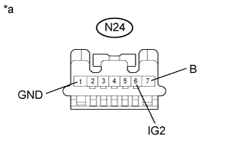
Text in Illustration *a Front view of wire harness connector
(to Steering Lock Actuator Assembly)
-
Disconnect the steering lock actuator assembly connector.
-
Measure the resistance according to the value(s) in the table below.
Standard Resistance Tester Connection Condition Specified Condition N24-1 (GND) - Body ground Always Below 1 Ω -
Measure the voltage according to the value(s) in the table below.
Standard Voltage Tester Connection Condition Specified Condition N24-7 (B) - Body ground Always 11 to 14 V N24-6 (IG2) - Body ground Power switch on (IG) 11 to 14 V
NG
REPAIR OR REPLACE HARNESS OR CONNECTOR
OK
-
-
REPLACE STEERING LOCK ACTUATOR ASSEMBLY (STEERING LOCK ECU)
-
Temporarily replace the steering lock actuator with a new one Click here.
NEXT
-
-
CLEAR DTC
-
Clear the DTCs Click here.
NEXT
-
-
CHECK FOR DTC
-
Check for DTCs Click here.
OK DTC B2786 is not output.
NG
REPLACE CERTIFICATION ECU (SMART KEY ECU ASSEMBLY)
OK
END (STEERING LOCK ACTUATOR ASSEMBLY IS DEFECTIVE)
-