LIN COMMUNICATION SYSTEM, Diagnostic DTC:B2785

| DTC Code | DTC Name |
|---|---|
| B2785 | Communication Malfunction between ECUs Connected by LIN |
DESCRIPTION
The certification ECU (smart key ECU assembly) monitors the LIN communication bus between the components related to the certification intermittently. DTC B2785 is output when a malfunction in the LIN communication bus between the components related to the certification is detected continuously 3 times.
| DTC Code | DTC Detection Condition | Trouble Area |
|---|---|---|
| B2785 | Certification ECU (smart key ECU assembly) detects malfunction in LIN communication bus between components related to certification continuously 3 times |
|
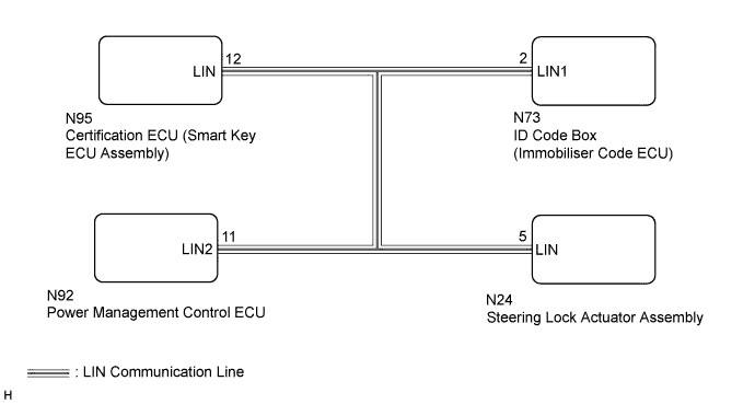
WIRING DIAGRAM
INSPECTION PROCEDURE
Note
-
When using the GTS with the power switch off to troubleshoot:
Connect the GTS to the vehicle, and turn a courtesy switch on and off at 1.5 second intervals until communication between the GTS and vehicle begins.
-
Before replacing the certification ECU (smart key ECU assembly), refer to the entry and start system (for Entry Function) Click here.
Tech Tips
When DTC B2785 and B2287 are output simultaneously, perform the troubleshooting for DTC B2785 first.
PROCEDURE
-
CLEAR DTC
-
Clear the DTCs Click here.
NEXT 
-
-
CHECK FOR DTC
-
Check for DTCs Click here.
Result Result Proceed to DTC B2785 is output A DTC B2785 is not output B
B 
USE SIMULATION METHOD TO CHECK Click here
A
-
-
CHECK HARNESS AND CONNECTOR (CERTIFICATION ECU [SMART KEY ECU ASSEMBLY] - ID CODE BOX [IMMOBILISER CODE ECU] - POWER MANAGEMENT CONTROL ECU OR STEERING LOCK ACTUATOR ASSEMBLY)
-
Disconnect the N95 certification ECU (smart key ECU assembly) connector.
-
Disconnect the N73 ID code box (immobiliser code ECU) connector.
-
Disconnect the N92 power management control ECU connector.
-
Disconnect the N24 steering lock actuator assembly connector.
-
Measure the resistance according to the value(s) in the table below.
Standard Resistance Tester Connection Condition Specified Condition N95-12 (LIN) - N24-5 (LIN) Always Below 1 Ω N95-12 (LIN) - N92-11 (LIN2) Always Below 1 Ω N95-12 (LIN) - N73-2 (LIN1) Always Below 1 Ω N95-12 (LIN) - Body ground Always 10 kΩ or higher
NG
REPAIR OR REPLACE HARNESS OR CONNECTOR
OK
-
-
CLEAR DTC
-
Clear the DTCs Click here.
NEXT
-
-
CHECK FOR DTC
-
Disconnect the N24 steering lock actuator assembly connector.
-
Check for DTCs Click here.
Result Result Proceed to DTC B2785 is output A DTC B2785 is not output B
B
REPLACE STEERING LOCK ACTUATOR ASSEMBLY Click here
A
-
-
CLEAR DTC
-
Clear the DTCs Click here.
NEXT
-
-
CHECK FOR DTC
-
Disconnect the N73 ID code box (immobiliser code ECU) connector.
-
Check for DTCs Click here.
Result Result Proceed to DTC B2785 is output A DTC B2785 is not output B
B
REPLACE ID CODE BOX (IMMOBILISER CODE ECU)
A
-
-
CLEAR DTC
-
Clear the DTCs Click here.
NEXT
-
-
CHECK FOR DTC
-
Disconnect the N92 power management control ECU connector.
-
Check for DTCs Click here.
Result Result Proceed to DTC B2785 is output A DTC B2785 is not output B
B
REPLACE POWER MANAGEMENT CONTROL ECU Click here
A 
REPLACE CERTIFICATION ECU (SMART KEY ECU ASSEMBLY)
-