INTEGRATION RELAY ON-VEHICLE INSPECTION

-
INSPECT NO. 2 INTEGRATION RELAY
Note
Both present and history signal readings will be cleared if the No. 2 integration relay is removed. Make sure not to remove it before inspection.
Tech Tips
-
This is an inspection to check whether or not there is an electrical load malfunction (past or current) in the system connected to the No. 2 integration relay. This does not check if the No. 2 integration relay is functioning normally.
-
The No. 2 integration relay outputs signals by changing the voltage output from the diagnosis terminal.
-
If it is determined that there is a malfunction during the inspection of the integration relay, the malfunction is recorded as a history signal when the electrical load switch turns OFF.
-
After repairing the wire harness, make sure to disconnect the cable from the negative battery terminal to clear the signal readings.
-
Inspect the diagnosis terminal (present signal reading).
-
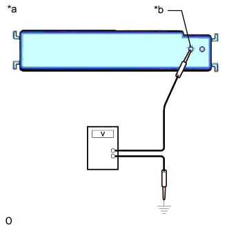
Text in Illustration *a Component with harness connected
(No. 2 Integration Relay)
*b Diagnosis Terminal 0 Measure the voltage between the diagnosis terminal and body ground.
Standard Voltage Tester Connection Switch Condition Specified Condition Diagnosis Terminal 0 - Body ground Power switch off, taillights illuminated (Battery voltage - 2.0 V) or higher (there is no malfunction)
Battery voltage is 0.5 V or less (there is a malfunction)
Power switch off, headlights illuminated*1 Power switch off, fog lights illuminated*1 Power switch off, brake lights illuminated Power switch on (IG)*2 Power switch on (IG), daytime running lights illuminated*3 Power switch on (IG), window defogger operating*3
-
*1 Check that there is no malfunction when the taillight switch is on.
-
*2 If there is a malfunction when the power switch is on (IG) and the electrical load switch is OFF, there may be a rear sunshade malfunction.
-
*3 Check that there is no malfunction when the power switch is on (IG) and the electrical load switch is OFF.
Tech Tips
-
If the battery voltage is 0.5 V or less, there may be an electrical malfunction with the system connected to the No. 2 integration relay.
-
An abnormal present signal output can be cleared by disconnecting the cable from the negative battery terminal (waiting time of 1 minute).
-
-
-
Inspect the diagnosis terminal (history signal reading).
-
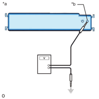
Text in Illustration *a Component with harness connected
(No. 2 Integration Relay)
*b Diagnosis Terminal 1 Measure the resistance between the diagnosis terminal and body ground.
Standard Voltage Tester Connection Switch Condition Specified Condition Diagnosis Terminal 1 - Body Ground Power switch off, taillights illuminated (Battery voltage - 2.0 V) or higher (there is no malfunction)
Battery voltage is 0.5 V or less (there is a malfunction)
Power switch off, headlights illuminated*1 Power switch off, fog lights illuminated*1 Power switch off, brake lights illuminated Power switch on (IG)*2 Power switch on (IG), daytime running lights illuminated*3 Power switch on (IG), window defogger operating*3
-
*1 Check that there is no malfunction when the taillight switch is on.
-
*2 If there is a malfunction when the power switch is on (IG) and the electrical load switch is OFF, there may be a rear sunshade malfunction.
-
*3 Check that there is no malfunction when the power switch is on (IG) and the electrical load switch is OFF.
Tech Tips
-
If the battery voltage is 0.5 V or less, there may be an electrical malfunction with the system connected to the No. 2 integration relay.
-
An abnormal history signal output can be cleared by disconnecting the cable from the negative battery terminal (waiting time of 1 minute).
-
-
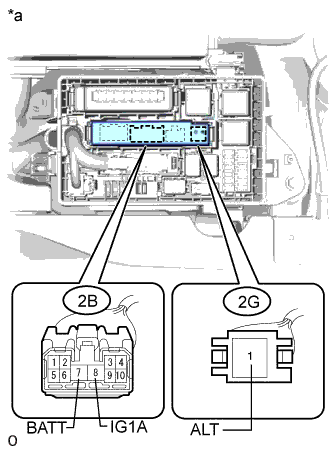
Text in Illustration *a Component without harness connected
(No. 1 Engine Room Relay block assembly)
If no signal readings are output, perform troubleshooting according to the following troubleshooting procedure.
-
Remove the No. 2 integration relay Click here.
-
Measure the voltage according to the value(s) in the table below.
Standard Voltage Tester Connection Switch Condition Specified Condition 2B (IG1A) 8 - Body ground Power switch on (IG) 11 to 14 V 2B (BATT) 7 - Body ground Always 11 to 14 V 2G (ALT) 1 - Body ground Always 11 to 14 V Tech Tips
If the result is not as specified, repair or replace the wire harness or connector.
-
-
-