POWER MANAGEMENT CONTROL ECU INSTALLATION

Tech Tips
-
Use the same procedure for RHD and LHD vehicles.
-
The procedure listed below is for LHD vehicles.
-
INSTALL POWER MANAGEMENT CONTROL ECU
-
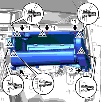
Install the power management control ECU with the 2 claws.
-
-
INSTALL ECU INTEGRATION BOX RH (for LHD)
-
Install the ECU integration box RH with the 2 nuts and bolt.
- Torque:
- 8.5 N*m { 87 kgf*cm, 75 in.*lbf }
-
Connect all the connectors.
Note
-
Do not twist the connectors of the ECUs when connecting them.
-
Do not apply more force than necessary to the connectors. If more than 98 N (10 kgf, 22 lbf) of force is applied to a connector, the connector or connector holder may be damaged.
-
-
-
INSTALL ECU INTEGRATION BOX LH (for RHD)
-
Install the ECU integration box LH with the 2 nuts and bolt.
- Torque:
- 8.5 N*m { 87 kgf*cm, 75 in.*lbf }
-
Connect all the connectors.
Note
-
Do not twist the connectors of the ECUs when connecting them.
-
Do not apply more force than necessary to the connectors. If more than 98 N (10 kgf, 22 lbf) of force is applied to a connector, the connector or connector holder may be damaged.
-
-
-
INSTALL COWL SIDE JUNCTION BLOCK RH (for LHD)
-
Connect the 2 connectors.
-
Install the cowl side junction block RH to the reinforcement with the bolt and nut.
- Torque:
- Nut
- 8.0 N*m { 82 kgf*cm, 71 in.*lbf }
- Bolt
- 13 N*m { 127 kgf*cm, 9 ft.*lbf }
-
Connect the connector.
-
w/o VGRS System:
-
Attach the clamp.
-
Connect the connector.
-
-
w/ VGRS System:
-
Connect the 5 connectors.
-
Attach the 2 clamps.
-
-
-
INSTALL COWL SIDE JUNCTION BLOCK LH (for RHD)
-
Connect the 2 connectors.
Note
Be sure to connect each connector securely.
-
Install the instrument panel cowl side junction block LH with the bolt and nuts.
- Torque:
- nut
- 8.0 N*m { 82 kgf*cm, 71 in.*lbf }
- bolt
- 13 N*m { 133 kgf*cm, 10 ft.*lbf }
-
Connect the 7 connectors.
Note
Be sure to connect each connector securely.
-
w/ VGRS:
-
Attach the 2 clamps.
-
Connect the 5 connectors.
-
-
w/o VGRS:
-
Attach the clamp.
-
Connect the connector.
-
-
-
INSTALL GLOVE COMPARTMENT DOOR ASSEMBLY
Text in Illustration *1 Screw <A> *2 Bolt <E>
-
Connect the connectors and attach the clamp.
-
Attach the 6 clips to install the glove compartment door assembly.
-
Install the 3 screws <A> and 2 bolts <E>.
-
-
INSTALL NO. 2 INSTRUMENT PANEL UNDER COVER SUB-ASSEMBLY
-
Connect the connectors and attach the clamp.
-
Attach the 5 clips and 2 guides to install the No. 2 instrument panel under cover sub-assembly.
-
-
INSTALL CENTER INSTRUMENT CLUSTER FINISH PANEL
-
Connect the connector.
-
Attach the 9 clips and guide to install the center instrument cluster finish panel.
-
-
INSTALL INSTRUMENT PANEL FINISH PANEL END RH
-
Attach the 5 clips and 2 guides to install the instrument panel finish panel end RH.
-
-
INSTALL INSTRUMENT SIDE PANEL RH
-
w/ Airbag Cut Off Switch:
-
Connect the connector.
-
-
Attach the 7 clips to install the instrument side panel RH.
-
-
INSTALL FRONT DOOR OPENING TRIM COVER RH
Tech Tips
Use the same procedure described for the LH side.
-
INSTALL FRONT DOOR SCUFF PLATE RH
Tech Tips
Use the same procedure described for the LH side.
-
CONNECT CABLE TO AUXILIARY BATTERY NEGATIVE TERMINAL
Note
When disconnecting the cable, some systems need to be initialized after the cable is reconnected Click here.
-
INSTALL LUGGAGE COMPARTMENT TRIM COVER LH
-
Install the luggage compartment trim cover LH.
-
-
INSTALL LUGGAGE COMPARTMENT FLOOR MAT
-
Install the luggage compartment floor mat.
-