NIGHT VIEW CAMERA REMOVAL

Note
-
Do not touch the camera lens or the front windshield glass in front of the camera.
-
Do not use a camera which has been dropped or subjected to an impact. Do not drop the camera or subject it to an impact.
-
REMOVE INNER REAR VIEW MIRROR ASSEMBLY
-
REMOVE MAP LIGHT ASSEMBLY
-
w/ Night View System:
-
Using a moulding remover, detach the 2 claws A.
-
Using a moulding remover, detach the 2 clips A.
Tech Tips
When the 2 clips A are detached, claw B, guide B and the fastener may also become detached.
-
Detach the 2 clips B.
-
Move the hooks of the 2 guides forward, disconnect the connector, and remove the map light assembly together with the front roof top garnish.
Note
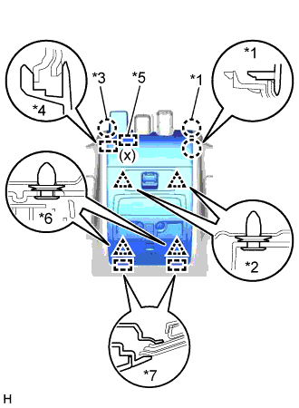
When removing the map light assembly together with the front roof top garnish, make sure not to apply excessive pressure to the camera sensor (x).
Tech Tips
If claw B, guide B and the fastener do not become detached when the 2 clips labeled A are detached, detach claw B, guide B, and the fastener to remove the map light assembly together with the front roof top garnish.
-
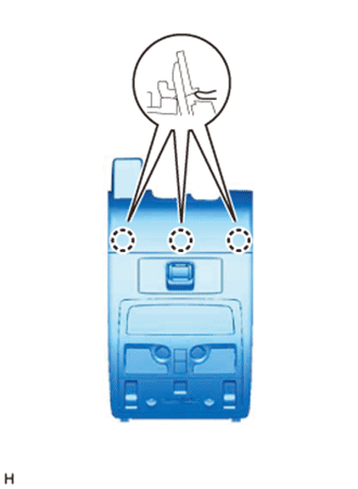
Text in Illustration *1 Claw A *2 Clip A *3 Claw B *4 Guide B *5 Fastener *6 Clip B *7 Guide A Detach the 3 claws on the back of the map light assembly and front roof top garnish, and disconnect the map light assembly and front roof top garnish.
-
-
w/o Night View System:
-
Using a moulding remover, detach the 2 claws A.
-
Using a moulding remover, detach the 2 clips A.
Tech Tips
When the 2 clips A are detached, claw B and guide B may also become detached.
-
Detach the 2 clips B.
-
Move the hooks of the 2 guides forward, disconnect the connector, and remove the map light assembly together with the front roof top garnish.
Note
w/ Lane Keeping Assist System:
When removing the map light assembly together with the front roof top garnish, make sure not to apply excessive pressure to the camera sensor (x).
Tech Tips
If claw B and guide B do not become detached when the 2 clips labeled A are detached, detach claw B and guide B to remove the map light assembly together with the front roof top garnish.
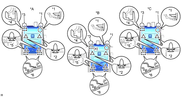
Text in Illustration *A for Standard *B w/ Lane Keeping Assist System *C w/ Rain Sensor - - *1 Claw A *2 Clip A *3 Claw B *4 Guide B *5 Clip B *6 Guide A -
Detach the 3 claws on the back of the map light assembly and front roof top garnish, and disconnect the map light assembly and front roof top garnish.
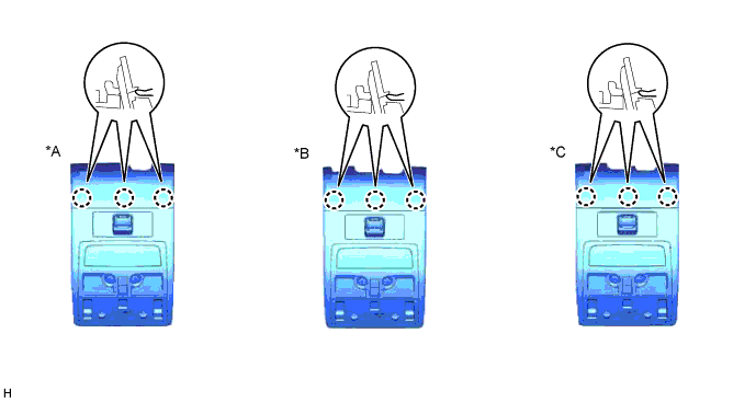
Text in Illustration *A for Standard *B w/ Lane Keeping Assist System *C w/ Rain Sensor - -
-
-
-
REMOVE VISOR BRACKET COVER
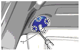
Text in Illustration *1 Protective Tape Tech Tips
Use the same procedure for both visor bracket covers.
-
Using a screwdriver, detach the 4 claws and remove the visor bracket cover.
-
-
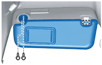
REMOVE VISOR ASSEMBLY LH
-
Detach the guide.
-
Remove the 2 screws and visor assembly LH.
-
-
REMOVE VISOR ASSEMBLY RH
Tech Tips
Use the same procedure described for the LH side.
-
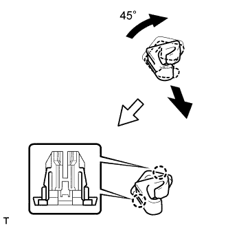
REMOVE VISOR HOLDER
Tech Tips
Use the same procedure for both visor holders.
-
Turn the visor holder clockwise approximately 45° and pull it out as shown in the illustration.
-
Detach the 2 claws and remove the visor holder.
-
-
REMOVE NIGHT VIEW CAMERA ASSEMBLY
Note
Do not drop or subject the camera to strong shocks.
-
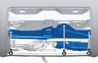
Remove the 3 bolts.
-
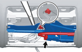
Using a moulding remover, detach the clip and remove the night view camera assembly.
Note
Do not touch the lens of the camera sensor during removal.
-
Disconnect the connector.
-