NIGHT VIEW SYSTEM Multi-display does not Change to Night View Screen
DESCRIPTION
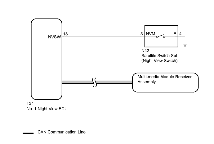
When the No. 1 night view ECU receives the switch signal from the night view switch, the ECU outputs a night view display request signal to the multi-media module receiver assembly.
WIRING DIAGRAM
INSPECTION PROCEDURE
Note
When the No. 1 night view ECU is replaced, perform night view camera adjustment Click here.
PROCEDURE
-
CHECK FOR DTC
-
Connect the GTS to the DLC3.
-
Turn the power switch on (IG) and turn the GTS on.
-
Enter the following menus: System Select / Health Check.
-
Clear the DTCs.
-
Turn the power switch off.
-
Wait 6 seconds after turning the power switch off, and then turn the power switch on (IG).
-
Enter the following menus: System Select / Health Check.
-
Check for DTCs.
Result Result Proceed to DTC is not output A Night view system DTC is output B CAN communication system DTC is output (for LHD) C CAN communication system DTC is output (for RHD) D
B 
GO TO DTC CHART Click here
C
GO TO CAN COMMUNICATION SYSTEM Click here
D
GO TO CAN COMMUNICATION SYSTEM Click here
A 
-
-
READ VALUE USING GTS (NIGHT VIEW MAIN SWITCH)
-
Using the GTS, read the Data List Click here.
Night View Tester Display Measurement Item/Range Normal Condition Diagnostic Note Night View Main Switch Status of night view switch / ON or OFF ON: Night view switch on
OFF: Night view switch off
"ON" is output while the night view switch is being pressed. OK The display is as specified in the normal condition column.
NG 
INSPECT SATELLITE SWITCH SET Click here
OK
-
-
REPLACE NO. 1 NIGHT VIEW ECU
-
Temporarily replace the No. 1 night view ECU with a new or normally functioning one Click here.
NEXT
-
-
ADJUST NIGHT VIEW CAMERA ASSEMBLY
-
Perform night view camera adjustment Click here.
NEXT
-
-
CHECK SYMPTOMS
-
Confirm that the "Multi-display does not Change to Night View Screen" problem symptom is not present.
OK Symptom is not present.
NG
GO TO NAVIGATION SYSTEM Click here
OK 
END (NO. 1 NIGHT VIEW ECU IS DEFECTIVE)
-
-
INSPECT SATELLITE SWITCH SET
-
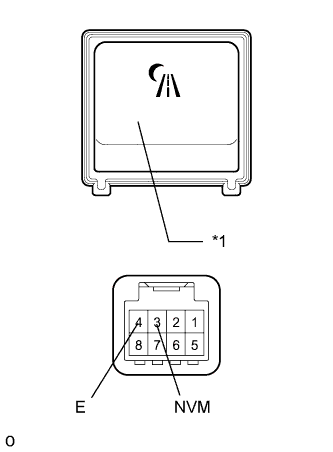
Text in Illustration *1 Night View Switch Remove the satellite switch set Click here.
-
Measure the resistance according to the value(s) in the table below.
Standard Resistance Tester Connection Switch Condition Specified Condition 3 (NVM) - 4 (E) Night view switch on Below 1 Ω Night view switch off 10 kΩ or higher
NG
REPLACE SATELLITE SWITCH SET Click here
OK
-
-
CHECK HARNESS AND CONNECTOR (SATELLITE SWITCH SET [NIGHT VIEW SWITCH] - NO. 1 NIGHT VIEW ECU AND BODY GROUND)
-
Disconnect the N42 satellite switch set (night view switch) connector.
-
Disconnect the T34 No. 1 night view ECU connector.
-
Measure the resistance according to the value(s) in the table below.
Standard Resistance Tester Connection Condition Specified Condition N42-3 (NVM) - T34-13 (NVSW) Always Below 1 Ω N42-4 (E) - Body ground N42-3 (NVM) - Body ground Always 10 kΩ or higher
NG
REPAIR OR REPLACE HARNESS OR CONNECTOR
OK
REPLACE NO. 1 NIGHT VIEW ECU Click here
-