NIGHT VIEW SYSTEM, Diagnostic DTC:B2825

| DTC Code | DTC Name |
|---|---|
| B2825 | Automatic Light Control Sensor Invalid Value |
DESCRIPTION
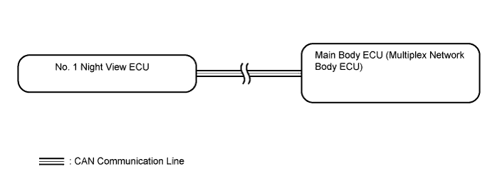
The No. 1 night view ECU receives automatic light control signals from the main body ECU via CAN communication. This DTC is stored when an automatic light control signal malfunction is detected.
Tech Tips
While DTCs are stored, the night view system does not operate and a warning message is displayed on the accessory meter assembly.
| DTC Code | DTC Detection Condition | Trouble Area |
|---|---|---|
| B2825 | The No. 1 night view ECU continuously receives abnormal automatic light control information for 3 seconds. |
|
WIRING DIAGRAM
INSPECTION PROCEDURE
Note
When the No. 1 night view ECU is replaced, perform night view camera adjustment Click here.
PROCEDURE
-
CHECK FOR DTC (CAN COMMUNICATION SYSTEM)
-
Use the GTS to check if the CAN communication system is functioning normally.
-
CAN communication system (for LHD): Click here
-
CAN communication system (for RHD): Click here
Result Result Proceed to CAN DTC is not output A CAN DTC is output (for LHD) B CAN DTC is output (for RHD) C -
B 
GO TO CAN COMMUNICATION SYSTEM Click here
C
GO TO CAN COMMUNICATION SYSTEM Click here
A 
-
-
READ VALUE USING GTS (ILLUMINATION RATE INFORMATION)
-
Using the GTS, read the Data List Click here.
Main Body Tester Display Measurement Item/Range Normal Condition Diagnostic Note Illumination Rate Info Illumination rate information / 0 ms. to 2162.65 ms. Value output according to ambient light levels - OK The display is as specified in the normal condition column.
NG
GO TO LIGHTING SYSTEM Click here
OK 
REPLACE NO. 1 NIGHT VIEW ECU Click here
-