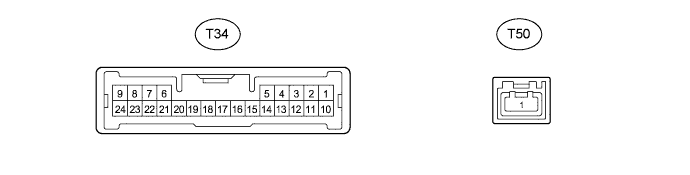
NIGHT VIEW SYSTEM TERMINALS OF ECU

-
CHECK NO. 1 NIGHT VIEW ECU
-
Disconnect the T34 No. 1 night view ECU connector.
-
Measure the resistance and voltage according to the value(s) in the table below.
Terminal No. (Symbol) Wiring Color Terminal Description Condition Specified Condition T34-6 (RE) - Body ground W-B - Body ground Ground Always Below 1 Ω T34-10 (IG) - Body ground GR - Body ground IG power supply Power switch off Below 1 V Power switch on (IG) 11 to 14 V If the result is not as specified, there may be a malfunction on the wire harness side.
-
Reconnect the T34 No. 1 night view ECU connector.
-
Measure the voltage according to the value(s) in the table below.
Terminal No. (Symbol) Wiring Color Terminal Description Condition Specified Condition T34-3 (IRFR) - T34-6 (RE) P - W-B Right side near-infrared ray emitter monitoring signal Night view system operating (forcibly operated using Active Test) Pulse generation
(See waveform 1)
T34-4 (LPFL) - T34-6 (RE)*1 GR - W-B Low beam headlight illumination state monitoring signal Power switch on (IG), low beam headlights illuminated 3.68 to 6 V*2,*3 T34-12 (IRFL) - T34-6 (RE) L - W-B Left side near-infrared ray emitter monitoring signal Night view system operating (forcibly operated using Active Test) Pulse generation
(See waveform 1)
T34-13 (NVSW) - T34-6 (RE) W - W-B Night view switch signal Power switch on (IG), night view switch on Below 1 V Power switch on (IG), night view switch off 4.8 to 5.2 V T34-15 (IRLY) - T34-6 (RE) LG - W-B Near-infrared ray emitter operation signal Night view system operating (forcibly operated using Active Test) 1.76 V or more T34-17 (CCD+) - T34-20 (CCD-) W - G Night view camera power supply Night view system operating (forcibly operated using Active Test) 5.7 to 6.5 V T34-18 (NTSC) - T34-6 (RE) B - W-B Night view camera NTSC signal Night view system operating and image output to accessory meter Pulse generation
(See waveform 2)
T34-19 (CLTS) - T34-6 (RE) R - W-B Night view camera control signal GTS in use (camera adjustment mode) Pulse generation T34-21 (SG) - T34-6 (RE) Shielded - W-B Night view camera shielded GND Always Below 1 V
-
*1: for HID Headlight
-
*2: When the auxiliary battery voltage is 10.5 V.
-
*3: The specified value varies depending on the battery voltage.
-
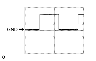
Waveform 1
Item Content Terminal No. (Symbol)
-
T34-3 (IRFR) - T34-6 (RE)
-
T34-12 (IRFL) - T34-6 (RE)
Tool setting 5 V/DIV., 40 ms./DIV. Condition Night view system operating (forcibly operated using Active Test) -
-
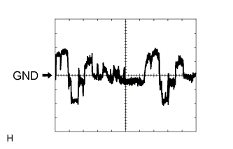
Waveform 2
Item Content Terminal No. (Symbol) T34-18 (NTSC) - T34-6 (RE) Tool setting 200 mV/DIV., 10 μs./DIV. Condition Night view system operating and image output to accessory meter
-
-