NIGHT VIEW SYSTEM SYSTEM DESCRIPTION

-
COMMUNICATION SYSTEM
-
The night view system communicates with other devices using CAN and AVC-LAN communication and digital signals.
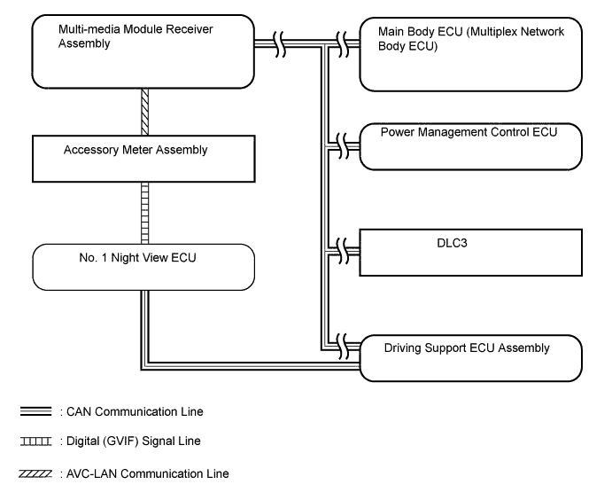
CAN Communication ECU Signal Input/Output No. 1 Night View ECU DTC information signal Output Various state signals Output Various request signals Output Various vehicle state signals Input Various tester request signals Input Main Body ECU (Multiplex Network Body ECU) Light sensor illuminance signal Output Low beam headlight illumination request signal Output Power Management Control ECU Shift position signal Output Multi-media Module Receiver Assembly Advice display request signal Input Night view display request signal Input Driving Support ECU Assembly Wiper system signal Output Vehicle speed signal Output Destination information signal Output DLC3 DTC read signal Input Camera adjustment signal Output Active Test signal Output Initial setting information signal Output Tech Tips
When there is a problem with the communication between ECUs, check the CAN communication system DTCs (for LHD Click here (for RHD Click here.
AVC-LAN Communication ECU Signal Input/Output Multi-media Module Receiver Assembly Advice display request signal Output Night view display request signal Output Accessory Meter Assembly Advice display request signal Input Night view display request signal Input Digital Signal ECU Signal No. 1 Night View ECU → Accessory Meter Assembly Video signal (GVIF)
-
-
SYSTEM DESCRIPTION
-
The night view system uses a camera to detect the near-infrared rays emitted from the near-infrared ray emitting portion of the headlight assembly, as well as reflected light from the headlights and surrounding light, and creates a black and white image based on the intensity of the light. This is used to aid nighttime visibility. The image is displayed on the accessory meter assembly.
Tech Tips
-
Depending on road and weather conditions, visibility (image quality) may vary.
-
The system cannot display all objects brightly. The image may be entirely dark, or parts of objects may be difficult to see.
-
As the system sensitivity is calibrated for nighttime use, when the vehicle is in a bright area such as an area illuminated by street lights, or when the headlights of an oncoming vehicle are shining brightly, the image may become washed out (become white) and be unclear.
-
If the inner or outer surface of the windshield glass is dirty, the image may become unclear. In this case, clean the windshield glass.
-
When it is cold and the "FOOT" mode of the heater is used, the upper portion of the windshield glass may become clouded, resulting in the image becoming unclear. In this case, use the "DEF" mode and clear the windshield glass.
-
If the headlight assembly is dirty, the image may become unclear. In this case, clean the headlight assembly.
-
When the auxiliary battery voltage is low, the image darkens. In this case, charge the auxiliary battery or replace it with a new one.
-
-
-
OPERATION CONDITIONS
-
The night view system operates when the night view switch is pushed after the automatic light control sensor has determined from the ambient brightness that it is nighttime, and the headlights are illuminated.
Operation Conditions Operation Condition Operation Condition
(Vehicle Speed)
Near-infrared Ray Emitter
-
The power switch is on (IG).
-
The surrounding area is dark.
-
The headlights are illuminated.
-
The night view switch is on.
Approximately 15 km/h (9.3 mph) or less Off* Approximately 15 km/h (9.3 mph) or more On Tech Tips
-
*: The night view image is displayed, but the area and distance that can be displayed are limited as near-infrared rays are not being emitted.
-
The night view switch must be turned on each time the power switch is turned from off to on (IG).
-
-