NIGHT VIEW SYSTEM, Diagnostic DTC:B281C

| DTC Code | DTC Name |
|---|---|
| B281C | Near Infrared Camera Sync Signal is not received |
DESCRIPTION
The No. 1 night view ECU monitors the synchronization signal of the night view camera. This DTC is stored when a synchronization signal malfunction is detected.
Tech Tips
While DTCs are stored, the night view system does not operate and a warning message is displayed on the accessory meter assembly.
| DTC Code | DTC Detection Condition | Trouble Area |
|---|---|---|
| B281C | There is an NTSC signal synchronization problem. |
|
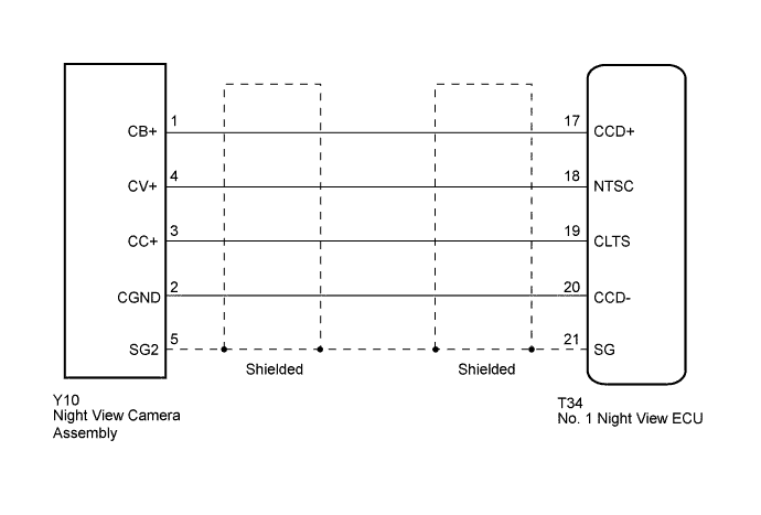
WIRING DIAGRAM
INSPECTION PROCEDURE
Note
When the No. 1 night view ECU or night view camera is replaced, perform night view camera adjustment Click here.
PROCEDURE
-
CHECK HARNESS AND CONNECTOR (NO. 1 NIGHT VIEW ECU - NIGHT VIEW CAMERA ASSEMBLY)
-
Disconnect the T34 No. 1 night view ECU connector.
-
Disconnect the Y10 night view camera assembly connector.
-
Measure the resistance according to the value(s) in the table below.
Standard Resistance Tester Connection Condition Specified Condition T34-17 (CCD+) - Y10-1 (CB+) Always Below 1 Ω T34-18 (NTSC) - Y10-4 (CV+) T34-19 (CLTS) - Y10-3 (CC+) T34-20 (CCD-) - Y10-2 (CGND) T34-21 (SG) - Y10-5 (SG2) T34-17 (CCD+) - Body ground Always 10 kΩ or higher T34-18 (NTSC) - Body ground T34-19 (CLTS) - Body ground T34-20 (CCD-) - Body ground T34-21 (SG) - Body ground
NG 
REPAIR OR REPLACE HARNESS OR CONNECTOR
OK 
-
-
CHECK NO. 1 NIGHT VIEW ECU
-
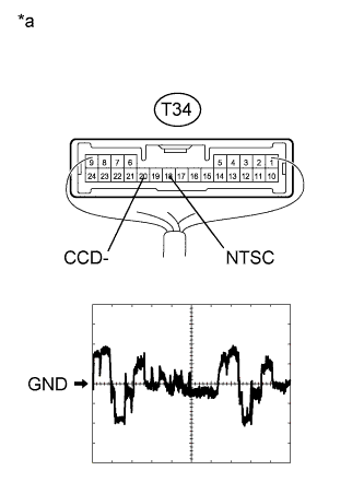
Text in Illustration *a Component with harness connected
(No. 1 Night View ECU)
Using the GTS, follow the instructions to switch to the "Night View" screen and select "Active Test".
-
Select "Night View System Operation" on the screen and forcibly operate the night view system.
-
Measure the voltage according to the value(s) in the table below.
Measurement Condition Item Content Terminal No. (Symbol) T34-18 (NTSC) - T34-20 (CCD-) Tool setting 200 mV/DIV., 10 μs./DIV. Condition Night view system operating (forcibly operated using Active Test) and image output to accessory meter
NG
REPLACE NIGHT VIEW CAMERA ASSEMBLY Click here
OK 
REPLACE NO. 1 NIGHT VIEW ECU Click here
-