NIGHT VIEW SYSTEM, Diagnostic DTC:B281B

| DTC Code | DTC Name |
|---|---|
| B281B | Near Infrared Camera Power Supply Malfunction |
DESCRIPTION
The No. 1 night view ECU monitors the power supplied to the night view camera. This DTC is stored if a power supply malfunction is detected.
Tech Tips
While DTCs are stored, the night view system does not operate and a warning message is displayed on the accessory meter assembly.
| DTC Code | DTC Detection Condition | Trouble Area |
|---|---|---|
| B281B | When the night view system is operating, the voltage at the CCD+ terminal of the No. 1 night view ECU is not between 5.7 and 6.5 V for 1 second or more. |
|
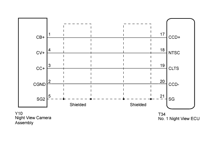
WIRING DIAGRAM
INSPECTION PROCEDURE
Note
When the No. 1 night view ECU or night view camera is replaced, perform night view camera adjustment Click here.
PROCEDURE
-
CHECK HARNESS AND CONNECTOR (NO. 1 NIGHT VIEW ECU - NIGHT VIEW CAMERA ASSEMBLY)
-
Disconnect the T34 No. 1 night view ECU connector.
-
Disconnect the Y10 night view camera assembly connector.
-
Measure the resistance according to the value(s) in the table below.
Standard Resistance Tester Connection Condition Specified Condition T34-17 (CCD+) - Y10-1 (CB+) Always Below 1 Ω T34-17 (CCD+) - Body ground Always 10 kΩ or higher
NG 
REPAIR OR REPLACE HARNESS OR CONNECTOR
OK 
-
-
CHECK NO. 1 NIGHT VIEW ECU
-
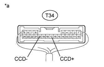
Text in Illustration *a Component with harness connected
(No. 1 Night View ECU)
Using the GTS, follow the instructions to switch to the "Night View" screen and select "Active Test".
-
Select "Night View System Operation" on the screen and forcibly operate the night view system.
-
Measure the voltage according to the value(s) in the table below.
Standard Voltage Tester Connection Condition Specified Condition T34-17 (CCD+) - T34-20 (CCD-) Night view system operating (forcibly operated using Active Test) 5.7 to 6.5 V
NG
REPLACE NO. 1 NIGHT VIEW ECU Click here
OK
-
-
REPLACE NIGHT VIEW CAMERA ASSEMBLY
-
Temporarily replace the night view camera assembly with a new or normally functioning one Click here.
NEXT
-
-
ADJUST NIGHT VIEW CAMERA ASSEMBLY
-
Perform night view camera adjustment Click here.
NEXT
-
-
CHECK FOR DTC
-
Clear the DTCs Click here.
-
Turn the power switch off.
-
Wait 6 seconds after turning the power switch off, and then turn the power switch on (IG).
-
Check for DTCs Click here.
OK DTC B281B is not output.
NG
REPLACE NO. 1 NIGHT VIEW ECU Click here
OK 
END (NIGHT VIEW CAMERA IS DEFECTIVE)
-