BLIND SPOT MONITOR SYSTEM OPERATION CHECK

-
Blind spot monitor beam axis inspection
-
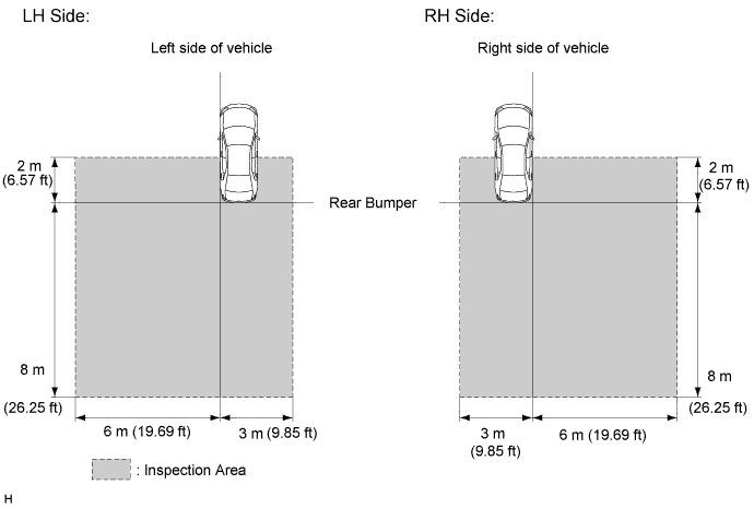
When performing the blind spot monitor beam axis inspection, move the vehicle to a place where the space shown in the illustration can be secured.
Note
-
Perform this inspection on level ground.
-
Make sure that there are no metal objects around the vehicle or on the ground.
-
Unload the vehicle before beginning the inspection.
-
Confirm that the tire pressure is correct before beginning the inspection.
-
Do not place an object other than the reflector (such as a large metallic object) in or allow people to enter the inspection area (W 9 m [29.52 ft.] x L 10 m [32.8 ft.] x H 4 m [13.2 ft.]) shown in the illustration.
-
Check that DTC C1ABB and DTC C1ABC are not output.
-
-
Procedure to enter the Test Mode
-
Connect the GTS to the DLC3.
-
Turn the power switch on (IG).
-
Turn the blind spot monitor main switch (integration control and panel assembly) on.
-
Turn the GTS on.
-
Switch the blind monitor sensor to Test Mode using the GTS. Enter the following menus: Body Electrical / Blind Spot Monitor Master / Utility / Test Mode.
-
-
Perform the blind spot monitor beam axis inspection.
-
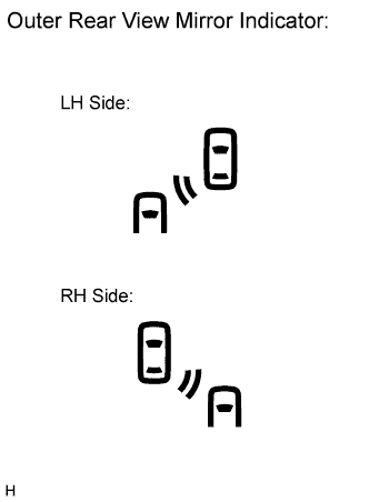
Check that the outer rear view mirror indicators are not illuminated.
Note
If an indicator is illuminated, the system is reacting to a piece of metal or some other object. In this case, move the vehicle to another place.
-
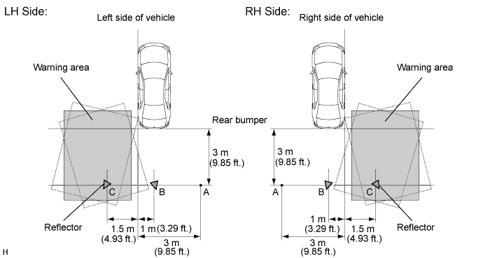
Place the reflector at position A.
- SST
- 09870-60000
- 09870-60010
- 09870-60040
Tech Tips
Set the reflector so that its center is 450 mm (1.48 ft.) above the floor.
-
Enter Test Mode using the GTS. Move the reflector from position A to B as shown in the illustration.
Tech Tips
-
Make sure that the orientation of the reflector is as shown in the illustration.
-
The acceptable range for sensor installation angle (horizontal direction) that allows the blind spot monitor system to operate correctly is as shown by the shaded areas inside the broken lines in the illustration (the warning areas).
Note
While moving the reflector, make sure that no one or no objects pass between the vehicle and the reflector.
-
-
After placing the reflector in the specified position, quickly exit the inspection area and make sure that objects other than the reflector are not in the inspection area and check that the outer rear view mirror indicator does not illuminate.
Tech Tips
If the indicator illuminates, repeat the same action (i.e. move the reflector from A to B). If the indicator illuminates again, check the blind spot monitor sensor installation condition.
-
Move the reflector from position B to C as shown in the illustration.
Tech Tips
Make sure that the orientation of the reflector is as shown in the illustration.
Note
While moving the reflector, make sure that no one or no objects pass between the vehicle and the reflector.
-
After placing the reflector in the specified position, quickly exit the inspection area and make sure that objects other than the reflector are not in the inspection area and check that the outer rear view mirror indicator illuminates.
Tech Tips
If the indicator does not illuminate, repeat the same action (i.e. move the reflector from B to C). If the indicator does not illuminate again, check the blind spot monitor sensor installation condition.
-
Finish Test Mode.
-
-
-
The Blind Spot Monitor Installation Condition Inspection
Note
-
Perform this inspection on level ground.
-
Unload the vehicle before beginning the inspection.
-
Confirm that the tire pressure is correct before beginning the inspection.
-
Remove the rear bumper Click here.
-
Attach a jig similar to the one shown in the illustration to the outward facing surface of the blind spot monitor sensor and check that the blind spot monitor sensor is perpendicular to the floor surface or within the allowable range.
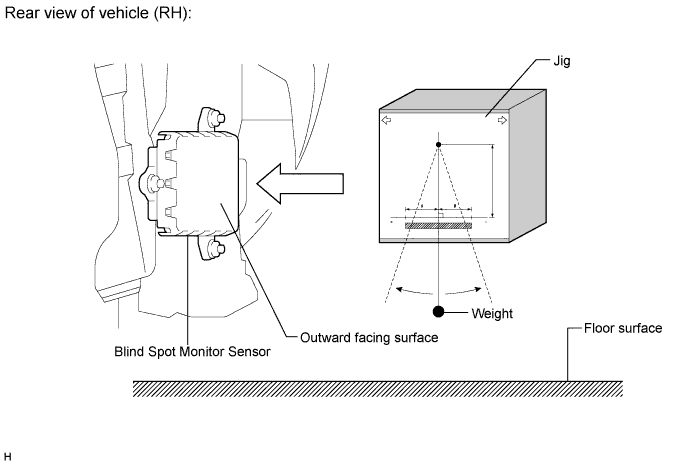
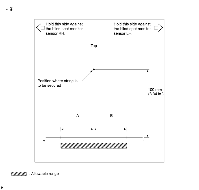
Standard A B Blind spot monitor sensor RH 17 mm (0.67 in.) -17 mm (-0.67 in.) Blind spot monitor sensor LH 8 mm (0.31 in.) -26 mm (-1.02 in.) Note
Allowable ranges A and B are different between the blind spot monitor sensor LH and RH.
-
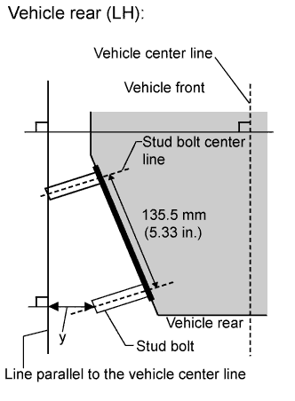
Using the sensor installation stud bolt center lines as a reference, check that the stud bolts are as shown in the illustration.
Standard Dimension Specified Value y 37 to 77 mm (1.46 to 3.03 in.)
-