AIR CONDITIONING SYSTEM Back-up Power Source Circuit
DESCRIPTION
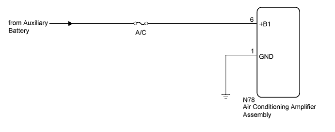
The back-up power source circuit for the air conditioning amplifier assembly is shown below. Power is supplied even when the power switch is off. The power is used for diagnostic trouble code memory, etc.
WIRING DIAGRAM
INSPECTION PROCEDURE
Note
-
Inspect the fuses for circuits related to this system before performing the following inspection procedure.
-
Before disconnecting the cable form the negative (-) battery terminal or replacing the air conditioning amplifier assembly, record the last operation state of the air conditioning for each transmitter. After replacement, it is necessary to perform memory registration for each transmitter Click here.
PROCEDURE
-
CHECK HARNESS AND CONNECTOR (AIR CONDITIONING AMPLIFIER ASSEMBLY - BATTERY)
-
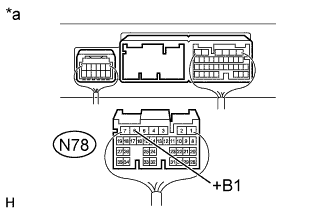
Text in Illustration *a Rear view of wire harness connector
(to Air Conditioning Amplifier Assembly)
Disconnect the air conditioning amplifier assembly connector.
-
Measure the voltage according to the value(s) in the table below.
Standard Voltage Tester Connection Condition Specified Condition N78-6 (+B1) - Body ground Always 11 to 14 V
NG 
REPAIR OR REPLACE HARNESS OR CONNECTOR
OK 
-
-
CHECK HARNESS AND CONNECTOR (AIR CONDITIONING AMPLIFIER ASSEMBLY - BODY GROUND)
-
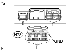
Text in Illustration *a Rear view of wire harness connector
(to Air Conditioning Amplifier Assembly)
Measure the resistance according to the value(s) in the table below.
Standard Resistance Tester Connection Condition Specified Condition N78-1 (GND) - Body ground Always Below 1 Ω
NG
REPAIR OR REPLACE HARNESS OR CONNECTOR
OK 
PROCEED TO NEXT SUSPECTED AREA SHOWN IN PROBLEM SYMPTOMS TABLE Click here
-