AIR CONDITIONING SYSTEM PTC Heater Circuit
DESCRIPTION
The air conditioning amplifier assembly sends operation signals to the PTC heater relays when quick heater assembly operation conditions are met. Based on the signals from the air conditioning amplifier assembly, the PTC heater relays turn on, and power is supplied to the quick heater assembly installed in the air conditioning radiator assembly.
| Control ECU | Condition |
|---|---|
| Air Conditioning Amplifier Assembly | Blower switch: Lo |
| Temperature set to HI | |
| ECO drive mode off | |
| Engine coolant temperature 64°C (147.2°F) or lower | |
| Ambient temperature 10°C (50.0°F) or lower | |
| IDH signal terminal: Below 1 V |
Tech Tips
-
When all operation conditions are met, 2 quick heater assemblies are operated.
-
The number of quick heater assemblies operated changes according to the engine coolant temperature.
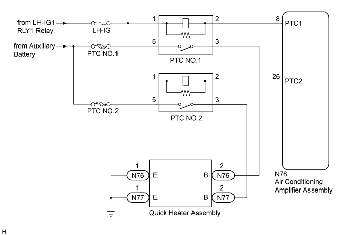
WIRING DIAGRAM
INSPECTION PROCEDURE
Note
-
When the auxiliary battery is disconnected or the air conditioning amplifier assembly is replaced, be sure to perform servo motor initialization Click here.
-
Inspect the fuses for circuits related to this system before performing the following inspection procedure.
-
Before disconnecting the cable form the negative (-) battery terminal or replacing the air conditioning amplifier assembly, record the last operation state of the air conditioning for each transmitter. After replacement, it is necessary to perform memory registration for each transmitter Click here.
PROCEDURE
-
PERFORM ACTIVE TEST USING GTS (HEATER ACTIVE LEVEL)
-
Connect the GTS to the DLC3.
-
Turn the power switch on (IG).
-
Turn the GTS on.
-
Enter the following menus: Body Electrical / Air Conditioner / Active Test Click here.
-
Check the operation by referring to the table below.
Air Conditioner Tester Display Test Part Control Range Diagnostic Note Heater Active Level Quick heater assembly Min.: 0, Max.: 2 - OK Heater Active Level changes normally.
NG 
INSPECT PTC HEATER RELAY (PTC NO.1, PTC NO.2) Click here
OK 
PROCEED TO NEXT SUSPECTED AREA SHOWN IN PROBLEM SYMPTOMS TABLE Click here
-
-
INSPECT PTC HEATER RELAY (PTC NO.1, PTC NO.2)
-
Remove the PTC heater relays Click here.
-
Inspect the PTC heater relays Click here.
NG 
REPLACE PTC HEATER RELAY Click here
OK 
-
-
CHECK HARNESS AND CONNECTOR (PTC HEATER RELAY - AIR CONDITIONING AMPLIFIER ASSEMBLY AND BATTERY)
-
Disconnect the N78 air conditioning amplifier assembly connector.
-
Measure the voltage according to the value(s) in the table below.
Standard Voltage Tester Connection Condition Specified Condition 5 - Body ground Always 11 to 14 V 1 - Body ground Power switch on (IG) 11 to 14 V 1 - Body ground Power switch off Below 1 V -
Measure the resistance according to the value(s) in the table below.
Standard Resistance Tester Connection Condition Specified Condition 2 - N78-26 (PTC2) Always Below 1 Ω 2 - Body ground Always 10 kΩ or higher
NG
REPAIR OR REPLACE HARNESS OR CONNECTOR
OK
-
-
CHECK HARNESS AND CONNECTOR (QUICK HEATER ASSEMBLY - PTC HEATER RELAY AND BODY GROUND)
-
Disconnect the N76 and N77 quick heater assembly connector.
-
Measure the resistance according to the value(s) in the table below.
Standard Resistance PTC NO.1 Tester Connection Condition Specified Condition N76-2 (B) - 3 Always Below 1 Ω N76-1 (E) - Body ground Always Below 1 Ω N76-2 (B) - Body ground Always 10 kΩ or higher PTC NO.2 Tester Connection Condition Specified Condition N77-2 (B) - 3 Always Below 1 Ω N77-1 (E) - Body ground Always Below 1 Ω N77-2 (B) - Body ground Always 10 kΩ or higher
NG
REPAIR OR REPLACE HARNESS OR CONNECTOR
OK
-
-
INSPECT QUICK HEATER ASSEMBLY
-
Remove the quick heater assembly Click here.
-
Inspect the quick heater assembly Click here.
NG
REPLACE QUICK HEATER ASSEMBLY Click here
OK
REPLACE AIR CONDITIONING AMPLIFIER ASSEMBLY Click here
-