AIR CONDITIONING SYSTEM Heater Water Pump Circuit
DESCRIPTION
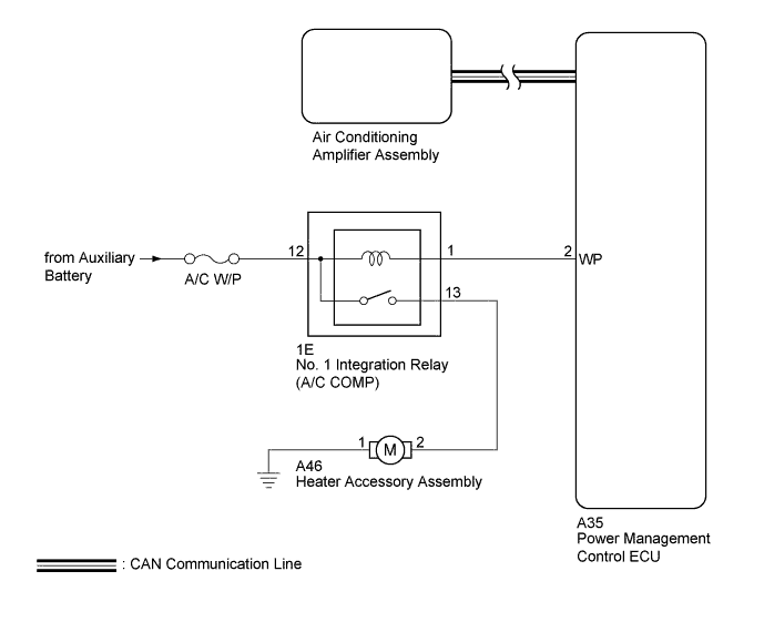
The heater accessory assembly sends engine coolant to the heater core assembly while the engine is stopped to prevent heater effectiveness from becoming low. Directed by the air conditioning amplifier assembly, the hybrid vehicle control ECU operates the water pump relay and drives the heater accessory assembly.
WIRING DIAGRAM
INSPECTION PROCEDURE
Note
Inspect the fuses for circuits related to this system before performing the following inspection procedure.
PROCEDURE
-
CHECK CAN COMMUNICATION SYSTEM
-
Use the GTS to check if the CAN communication system is functioning normally.
-
for LHD: Click here.
-
for RHD: Click here.
Result Result Proceed to CAN DTC is not output A CAN DTC is output (for LHD) B CAN DTC is output (for RHD) C -
B 
GO TO CAN COMMUNICATION SYSTEM Click here
C
GO TO CAN COMMUNICATION SYSTEM Click here
A 
-
-
INSPECT NO. 1 INTEGRATION RELAY
-
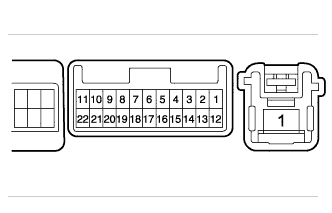
Remove the No. 1 integration relay.
-
Measure the resistance according to the value(s) in the table below.
Standard Resistance Tester Connection Condition Specified Condition 13 - Body ground When battery voltage is not applied between terminal 12 and 1 Below 1 V When battery voltage is applied between terminals 12 and 1 11 to 14 V
NG
REPLACE NO. 1 INTEGRATION RELAY
OK
-
-
INSPECT HEATER ACCESSORY ASSEMBLY
-
Remove the heater accessory assembly Click here.
-
Inspect the heater accessory assembly Click here.
NG
REPLACE HEATER ACCESSORY ASSEMBLY Click here
OK
-
-
CHECK HARNESS AND CONNECTOR (HEATER ACCESSORY ASSEMBLY - NO. 1 INTEGRATION RELAY, BATTERY AND BODY GROUND)
-
Measure the voltage according to the value(s) in the table below.
Standard Voltage Tester Connection Condition Specified Condition 1E-12 - Body ground Always 11 to 14 V -
Measure the resistance according to the value(s) in the table below.
Standard Resistance Tester Connection Condition Specified Condition A46-2 - 1E-13 Always Below 1 Ω A46-1 - Body ground Always Below 1 Ω A46-2 - Body ground Always 10 kΩ or higher
NG
REPAIR OR REPLACE HARNESS OR CONNECTOR
OK
-
-
CHECK HARNESS AND CONNECTOR (NO. 1 INTEGRATION RELAY - POWER MANAGEMENT CONTROL ECU)
-
Disconnect the A35 power management control ECU connector.
-
Measure the resistance according to the value(s) in the table below.
Standard Resistance Tester Connection Condition Specified Condition 1E-1 - A35-2 (WP) Always Below 1 Ω 1E-1 - Body ground Always 10 kΩ or higher
NG
REPAIR OR REPLACE HARNESS OR CONNECTOR
OK
-
-
CHECK POWER MANAGEMENT CONTROL ECU
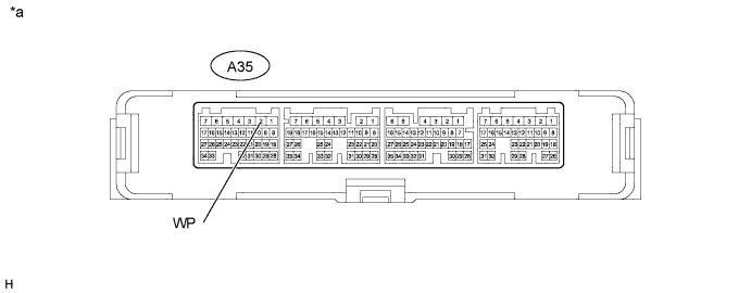
Text in Illustration *a Component with harness connected
(Power Management Control ECU)
- -
-
Reinstall the No. 1 integration relay.
-
Reconnect the A46 heater accessory assembly connector.
-
Reconnect the A35 power management control ECU connector.
-
Turning the power switch is on (Ready).
-
Measure the voltage according to the value(s) in the table below.
Standard Voltage Tester Connection Condition Specified Condition A35-2 (WP) - Body ground Air conditioning system operated Below 1 V A35-2 (WP) - Body ground Air conditioning system stopped 11 to 14 V
NG
REPLACE POWER MANAGEMENT CONTROL ECU Click here
OK 
PROCEED TO NEXT SUSPECTED AREA SHOWN IN PROBLEM SYMPTOMS TABLE Click here
-