AIR CONDITIONING SYSTEM, Diagnostic DTC:B14B9

| DTC Code | DTC Name |
|---|---|
| B14B9 | Open in Ion Generator Circuit |
DESCRIPTION
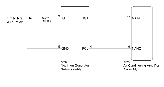
The No. 1 ion generator sub-assembly is controlled by the air conditioning amplifier assembly and operates in accordance with the blower with fan motor assembly. The air conditioning amplifier assembly sends a drive signal to the No. 1 ion generator sub-assembly. When the ion generator receives the drive signal and starts to operate, it outputs an operation condition signal to the air conditioning amplifier assembly.
| DTC Code | DTC Detection Condition | Trouble Area |
|---|---|---|
| B14B9 | Open in No. 1 ion generator sub-assembly circuit |
|
WIRING DIAGRAM
INSPECTION PROCEDURE
Note
-
Inspect the fuses for circuits related to this system before performing the following inspection procedure.
-
Before disconnecting the cable form the negative (-) battery terminal or replacing the air conditioning amplifier assembly, record the last operation state of the air conditioning for each transmitter. After replacement, it is necessary to perform memory registration for each transmitter Click here.
PROCEDURE
-
CHECK HARNESS AND CONNECTOR (NO. 1 ION GENERATOR SUB-ASSEMBLY - BODY GROUND)
-
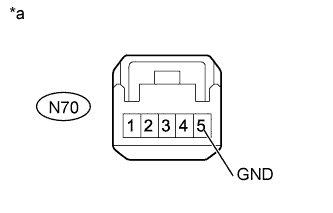
Text in Illustration *a Front view of wire harness connector
(to No. 1 Ion Generator Sub-assembly)
Disconnect the No. 1 ion generator sub-assembly connector.
-
Measure the resistance according to the value(s) in the table below.
Standard Resistance Tester Connection Condition Specified Condition N70-5 (GND) - Body ground Always Below 1 Ω
NG 
REPAIR OR REPLACE HARNESS OR CONNECTOR
OK 
-
-
CHECK HARNESS AND CONNECTOR (NO. 1 ION GENERATOR SUB-ASSEMBLY - BATTERY)
-
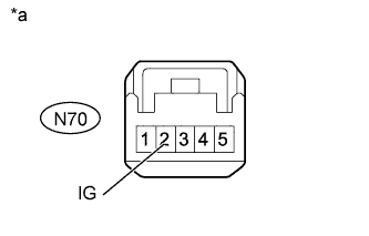
Text in Illustration *a Front view of wire harness connector
(to No. 1 Ion Generator Sub-assembly)
Measure the voltage according to the value(s) in the table below.
Standard Voltage Tester Connection Switch Condition Specified Condition N70-2 (IG) - Body ground Power switch off Below 1 V N70-2 (IG) - Body ground Power switch on (IG) 11 to 14 V
NG
REPAIR OR REPLACE HARNESS OR CONNECTOR
OK
-
-
CHECK HARNESS AND CONNECTOR (NO. 1 ION GENERATOR SUB-ASSEMBLY - AIR CONDITIONING AMPLIFIER ASSEMBLY)
-
Disconnect the N78 air conditioning amplifier assembly connector.
-
Measure the resistance according to the value(s) in the table below.
Standard Resistance Tester Connection Condition Specified Condition N78-22 (NAIN) - N70-1 (IG+) Always Below 1 Ω N78-9 (NANO) - N70-4 (PCL) Always Below 1 Ω N78-22 (NAIN) - Body ground Always 10 kΩ or higher N78-9 (NANO) - Body ground Always 10 kΩ or higher N78-22 (NAIN) - N78-9 (NANO) Always 10 kΩ or higher Result Result Proceed to NG A OK (When troubleshooting according to Problem Symptoms Table) B OK (When troubleshooting according to the DTC) C
B
PROCEED TO NEXT SUSPECTED AREA SHOWN IN PROBLEM SYMPTOMS TABLE Click here
C 
CHECK NO. 1 ION GENERATOR SUB-ASSEMBLY Click here
A 
REPAIR OR REPLACE HARNESS OR CONNECTOR
-
-
CHECK NO. 1 ION GENERATOR SUB-ASSEMBLY
-
Replace the No. 1 ion generator sub-assembly with a new or normally functioning one Click here.
Tech Tips
Since the No. 1 ion generator sub-assembly cannot be inspected while it is removed from the vehicle, replace the No. 1 ion generator sub-assembly with a new or a known good one and check that the condition returns to normal.
-
Check for DTC.
OK DTC B14B9 is not output.
NG
REPLACE AIR CONDITIONING AMPLIFIER ASSEMBLY Click here
OK
END (NO. 1 ION GENERATOR SUB-ASSEMBLY WAS DEFECTIVE)
-