AIR CONDITIONING SYSTEM, Diagnostic DTC:B14B3

| DTC Code | DTC Name |
|---|---|
| B14B3 | Lost Communication with Rear Panel LIN |
DESCRIPTION
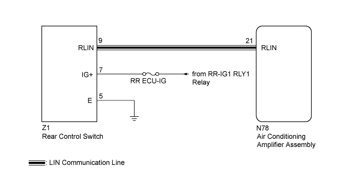
The rear control switch communicates with the air conditioning amplifier assembly through the LIN communication system.
If the LIN communication system malfunctions, the air conditioning amplifier assembly does not operate even if the rear control switch is operated.
| DTC Code | DTC Detection Condition | Trouble Area |
|---|---|---|
| B14B3 | Lost communication with the rear control switch. |
|
WIRING DIAGRAM
INSPECTION PROCEDURE
Note
-
Inspect the fuses and relays for circuits related to this system before performing the following inspection procedure.
-
When the auxiliary battery is disconnected or the air conditioning amplifier assembly is replaced, be sure to perform servo motor initialization Click here.
-
Before disconnecting the cable form the negative (-) battery terminal or replacing the air conditioning amplifier assembly, record the last operation state of the air conditioning for each transmitter. After replacement, it is necessary to perform memory registration for each transmitter Click here.
PROCEDURE
-
CHECK HARNESS AND CONNECTOR (REAR CONTROL SWITCH - BATTERY)
-
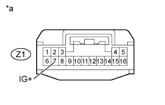
Text in Illustration *a Front view of wire harness connector
(to Rear Control Switch)
Disconnect the Z1 rear control switch connector.
-
Measure the voltage according to the value(s) in the table below.
Standard Voltage Tester Connection Switch Condition Specified Condition Z1-7 (IG+) - Body ground Power switch off Below 1 V Z1-7 (IG+) - Body ground Power switch on (IG) 11 to 14 V
NG 
REPAIR OR REPLACE HARNESS OR CONNECTOR
OK 
-
-
CHECK HARNESS AND CONNECTOR (REAR CONTROL SWITCH - BODY GROUND)
-
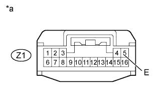
Text in Illustration *a Front view of wire harness connector
(to Rear Control Switch)
Measure the resistance according to the value(s) in the table below.
Standard Resistance Tester Connection Condition Specified Condition Z1-5 (E) - Body ground Always Below 1 Ω
NG
REPAIR OR REPLACE HARNESS OR CONNECTOR
OK
-
-
CHECK HARNESS AND CONNECTOR (AIR CONDITIONING AMPLIFIER ASSEMBLY - REAR CONTROL SWITCH)
-
Disconnect the N78 air conditioning amplifier assembly connector.
-
Measure the resistance according to the value(s) in the table below.
Standard Resistance Tester Connection Condition Specified Condition Z1-9 (RLIN) - N78-21 (RLIN) Always Below 1 Ω Z1-9 (RLIN) - Body ground Always 10 kΩ or higher
NG
REPAIR OR REPLACE HARNESS OR CONNECTOR
OK
-
-
CHECK REAR CONTROL SWITCH
-
Replace the rear control switch with new or normally functioning one Click here.
-
Check that the rear control switch operation returns to normal.
OK rear control switch operation returns to normal. Result Result Proceed to NG A OK (When troubleshooting according to Problem Symptoms Table) B OK (When troubleshooting according to the DTC) C
B
PROCEED TO NEXT SUSPECTED AREA SHOWN IN PROBLEM SYMPTOMS TABLE Click here
C
REPLACE AIR CONDITIONING AMPLIFIER ASSEMBLY Click here
A 
END (REAR CONTROL SWITCH WAS DEFECTIVE)
-