AIR CONDITIONING UNIT REASSEMBLY

Tech Tips
-
Use the same procedure for RHD and LHD vehicles.
-
The procedure listed below is for LHD vehicles.
-
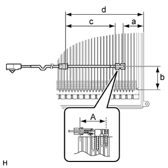
INSTALL COOLER THERMISTOR (FRONT EVAPORATOR TEMPERATURE SENSOR) (for 2GR-FXE)
Note
If reusing the evaporator, do not insert the sensor at a location where the sensor was previously inserted. Insert the sensor within range A shown in the illustration.
-
Insert the cooler thermistor (front evaporator temperature sensor) as shown in the illustration to install it.
Area Specified Condition a 34.3 mm (1.35 in.) b 50 mm (1.97 in.) c 123.5 mm (4.86 in.) d 175 mm (6.89 in.)
-
-
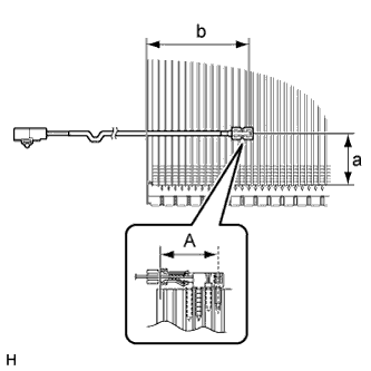
INSTALL COOLER THERMISTOR (FRONT EVAPORATOR TEMPERATURE SENSOR) (for 2AR-FSE)
Note
If reusing the evaporator, do not insert the sensor at a location where the sensor was previously inserted. Insert the sensor within range A shown in the illustration.
-
Insert the cooler thermistor (front evaporator temperature sensor) as shown in the illustration to install it.
Area Specified Condition a 50 mm (1.97 in.) b 101.3 mm (3.99 in.)
-
-
INSTALL NO. 1 COOLER EVAPORATOR SUB-ASSEMBLY
-
Sufficiently apply compressor oil to 2 new O-rings and the fitting surface of the hose joint.
Compressor oil ND-OIL 11 or equivalent -
Install the 2 O-rings to the No. 1 cooler evaporator sub-assembly.
-
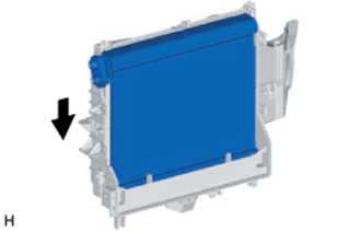
Install the No. 1 cooler evaporator sub-assembly as shown in the illustration.
-
Attach the 5 claws to install the air duct.
-
Install the 5 screws.
-
-
INSTALL NO. 2 AIR CONDITIONING RADIATOR DAMPER SERVO SUB-ASSEMBLY (for LH Side)
-
Install the No. 2 air conditioning radiator damper servo sub-assembly with the 2 screws.
-
-
INSTALL NO. 4 AIR CONDITIONING RADIATOR DAMPER SERVO SUB-ASSEMBLY
-
Install the No. 4 air conditioning radiator damper servo sub-assembly with the 2 screws.
-
-
INSTALL NO. 6 AIR CONDITIONING RADIATOR DAMPER SERVO SUB-ASSEMBLY
-
Install the No. 6 air conditioning radiator damper servo sub-assembly with the 3 screws.
-
-
INSTALL NO. 7 AIR CONDITIONING RADIATOR DAMPER SERVO SUB-ASSEMBLY
-
Install the No. 7 air conditioning radiator damper servo sub-assembly with the 2 screws.
-
-
INSTALL NO. 5 AIR CONDITIONING RADIATOR DAMPER SERVO SUB-ASSEMBLY (for 3 Zone)
-
Install the No. 5 air conditioning radiator damper servo sub-assembly with the 3 screws.
-
-
INSTALL NO. 3 AIR CONDITIONING RADIATOR DAMPER SERVO SUB-ASSEMBLY
-
Install the No. 3 air conditioning radiator damper servo sub-assembly with the 3 screws.
-
-
INSTALL NO. 2 AIR CONDITIONING RADIATOR DAMPER SERVO SUB-ASSEMBLY (for RH Side)
-
Install the No. 2 air conditioning radiator damper servo sub-assembly with the 2 screws.
-
-
INSTALL NO. 1 AIR CONDITIONING RADIATOR DAMPER SERVO SUB-ASSEMBLY
-
Install the No. 1 air conditioning radiator damper servo sub-assembly with the 2 screws.
-
-
INSTALL HEATER RADIATOR UNIT SUB-ASSEMBLY
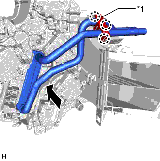
Text in Illustration *1 Clamp
-
Install the heater radiator unit sub-assembly as shown in the illustration.
-
Attach the 3 claws to install the clamp.
-
-
INSTALL COOLER EXPANSION VALVE
-
Install the cooler expansion valve.
-
-
INSTALL AIR CONDITIONING TUBE ASSEMBLY
-
Sufficiently apply compressor oil to 2 new O-rings and the fitting surface of the air conditioning tube assembly joint.
Compressor oil ND-OIL 11 or equivalent -
Install the 2 O-rings to the air conditioning tube assembly.
-
Using a 4 mm hexagon wrench, install the 2 hexagon bolts.
- Torque:
- 3.5 N*m { 36 kgf*cm, 31 in.*lbf }
-
Install new butyl tape.
-
Install new packing.
-
-
INSTALL AIR CONDITIONING HARNESS ASSEMBLY
-
Install the air conditioning harness assembly as shown in the illustration.
-
Connect the connectors.
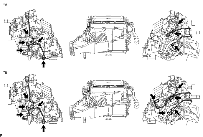
Text in Illustration *A for 2 Zone *B for 3 Zone
-
-
INSTALL BLOWER ASSEMBLY