PARKING ASSIST MONITOR SYSTEM TERMINALS OF ECU

-
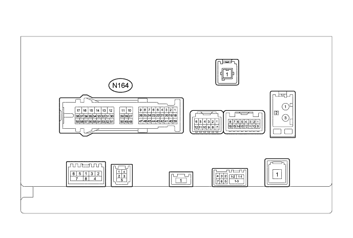
CHECK MULTI-MEDIA MODULE RECEIVER ASSEMBLY
-
Measure the voltage, resistance and check for pulses according to the value(s) in the table below.
Terminal No. (Symbol) Wiring Color Terminal Description Condition Specified Condition N164-39 (CA+) - N164-40 (CGND) B - Shielded Power source Hybrid control system starts, shift lever in R 5.5 to 7.05 V N164-18 (V+) - N164-40 (CGND) R - Shielded Display signal Hybrid control system starts, shift lever in R Pulse generation (See waveform) N164-19 (V-) - N164-40 (CGND) W - Shielded Rear television camera assembly ground Always Below 1 V N164-40 (CGND) - Body ground Shielded - Body ground Shielding Always Below 1 V N164-17 (+B1) - N164-12 (GND1) L - W-B Battery power source Always 11 to 14 V N164-12 (GND1) - Body ground W-B - Body ground Ground Always Below 1 Ω N164-1 (CANH) B CAN communication line - - N164-2 (CANL) W CAN communication line - - -
Using an oscilloscope, check waveform.
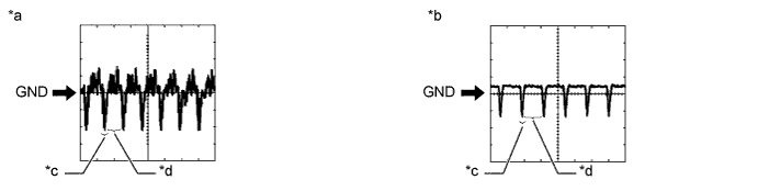
Text in Illustration *a Waveform A *b Waveform B *c Synchronization Signal *d Video Waveform Item Content Terminal No. (Symbol) N164-18 (V+) - N164-40 (CGND) Tool Setting 0.2 V/DIV., 50 μs/DIV. Condition Waveform A: Hybrid control system starts, shift lever in R (camera lens is not covered, displaying an image)
Waveform B: Hybrid control system starts, shift lever in R (camera lens is covered, blacking out the screen)
Tech Tips
The video waveform changes according to the image sent by the rear television camera assembly.
-
-
CHECK ACCESSORY METER ASSEMBLY (for 12.3 Inch), MULTI-DISPLAY (for 8 Inch)
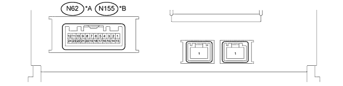
Text in Illustration *A for 12.3 Inch *B for 8 Inch
-
Measure the voltage and resistance according to the value(s) in the table below.
for 12.3 Inch Terminal No. (Symbol) Wiring Color Terminal Description Condition Specified Condition N62-12 (+B2) - Body ground SB - Body ground Battery power source Always 11 to 14 V N62-13 (GND1) - Body ground W-B - Body ground Ground Always Below 1 Ω N62-23 (IG) - Body ground LG - Body ground Power source (IG) Power switch on (IG) 11 to 14 V N62-24 (ACC) - Body ground GR - Body ground Power source (ACC) Power switch on (ACC) 11 to 14 V for 8 Inch Terminal No. (Symbol) Wiring Color Terminal Description Condition Specified Condition N155-12 (+B2) - Body ground SB - Body ground Auxiliary battery Always 11 to 14 V N155-13 (GND1) - Body ground W-B - Body ground Ground Always Below 1 Ω N155-23 (IG) - Body ground LG - Body ground Power source (IG) Power switch on (IG) 11 to 14 V N155-24 (ACC) - Body ground GR - Body ground Power source (ACC) Power switch on (ACC) 11 to 14 V
-