LEXUS PARKING ASSIST-SENSOR SYSTEM Clearance Warning ECU Power Source Circuit
DESCRIPTION
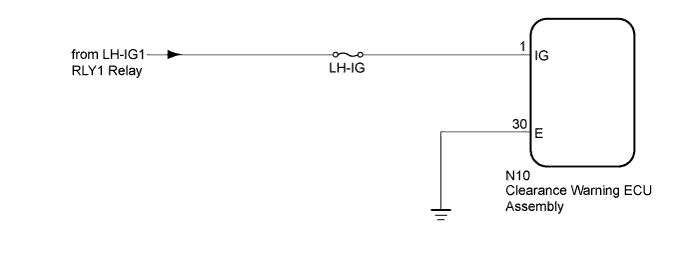
This circuit provides power to operate the clearance warning ECU assembly.
WIRING DIAGRAM
INSPECTION PROCEDURE
Note
Inspect the fuse for circuits related to this system before performing the following inspection procedure.
PROCEDURE
-
CHECK HARNESS AND CONNECTOR (CLEARANCE WARNING ECU ASSEMBLY - BATTERY)
-
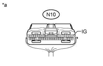
Text in Illustration *a Rear view of wire harness connector
(to Clearance Warning ECU Assembly)
Disconnect the connector from the clearance warning ECU assembly.
-
Measure the voltage according to the value(s) on the table below.
Standard Voltage Tester Connection Switch Condition Specified Condition N10-1 (IG) - Body ground Power switch on (IG) 11 to 14 V N10-1 (IG) - Body ground Power switch off Below 1 V
NG 
REPAIR OR REPLACE HARNESS OR CONNECTOR
OK 
-
-
CHECK HARNESS AND CONNECTOR (CLEARANCE WARNING ECU ASSEMBLY - BODY GROUND)
-
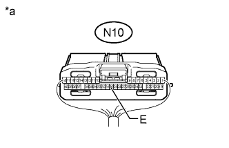
Text in Illustration *a Rear view of wire harness connector
(to Clearance Warning ECU Assembly)
Measure the resistance according to the value(s) in the table below.
Standard Resistance Tester Connection Condition Specified Condition N10-30 (E) - Body ground Always Below 1 Ω
NG
REPAIR OR REPLACE HARNESS OR CONNECTOR
OK 
PROCEED TO NEXT SUSPECTED AREA SHOWN IN PROBLEM SYMPTOMS TABLE Click here
-