LEXUS PARKING ASSIST-SENSOR SYSTEM, Diagnostic DTC:C1AEC

| DTC Code | DTC Name |
|---|---|
| C1AEC | Front Sensor Communication Malfunction |
DESCRIPTION
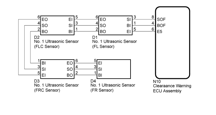
This DTC is stored when there is an open or short circuit in the communication line between the front sensors and the clearance warning ECU assembly, or when there is a malfunction in a front sensor.
| DTC Code | DTC Detection Condition | Trouble Area |
|---|---|---|
| C1AEC | An open or short circuit in the communication line between the front sensors and ECU or a malfunction in a front sensor during initialization mode after the power switch is turned on (IG). |
|
WIRING DIAGRAM
INSPECTION PROCEDURE
PROCEDURE
-
CHECK FOR DTC (C1AEC)
-
Clear the DTCs Click here.
-
Recheck for DTCs Click here.
Result Result Proceed to DTC C1AEC is output A No DTC is output B
B 
USE SIMULATION METHOD TO CHECK Click here
A 
-
-
CHECK HARNESS AND CONNECTOR (CLEARANCE WARNING ECU ASSEMBLY - NO. 1 ULTRASONIC SENSOR [FL SENSOR])
-
Disconnect the N10 clearance warning ECU assembly connector.
-
Disconnect the D1 No. 1 ultrasonic sensor (FL sensor) connector.
-
Measure the resistance according to the value(s) in the table below.
Standard Resistance Tester Connection Condition Specified Condition N10-4 (BOF) - D1-1 (BI) Always Below 1 Ω N10-8 (SOF) - D1-3 (SI) Always Below 1 Ω N10-6 (E5) - D1-5 (EI) Always Below 1 Ω N10-4 (BOF) - Body ground Always 10 kΩ or higher N10-8 (SOF) - Body ground Always 10 kΩ or higher N10-6 (E5) - Body ground Always 10 kΩ or higher
NG
REPAIR OR REPLACE HARNESS OR CONNECTOR
OK
-
-
CHECK HARNESS AND CONNECTOR (NO. 1 ULTRASONIC SENSOR [FL SENSOR] - NO. 1 ULTRASONIC SENSOR [FLC SENSOR])
-
Disconnect the D1 No. 1 ultrasonic sensor (FL sensor) connector.
-
Disconnect the D2 No. 1 ultrasonic sensor (FLC sensor) connector.
-
Measure the resistance according to the value(s) in the table below.
Standard Resistance Tester Connection Condition Specified Condition D1-2 (BO) - D2-1 (BI) Always Below 1 Ω D1-4 (SO) - D2-3 (SI) Always Below 1 Ω D1-6 (EO) - D2-5 (EI) Always Below 1 Ω D1-2 (BO) - Body ground Always 10 kΩ or higher D1-4 (SO) - Body ground Always 10 kΩ or higher D1-6 (EO) - Body ground Always 10 kΩ or higher
NG
REPAIR OR REPLACE HARNESS OR CONNECTOR
OK
-
-
CHECK HARNESS AND CONNECTOR (NO. 1 ULTRASONIC SENSOR [FLC SENSOR] - NO. 1 ULTRASONIC SENSOR [FRC SENSOR])
-
Disconnect the D2 No. 1 ultrasonic sensor (FLC sensor) connector.
-
Disconnect the D3 No. 1 ultrasonic sensor (FRC sensor) connector.
-
Measure the resistance according to the value(s) in the table below.
Standard Resistance Tester Connection Condition Specified Condition D2-2 (BO) - D3-1 (BI) Always Below 1 Ω D2-4 (SO) - D3-3 (SI) Always Below 1 Ω D2- 6 (EO) - D3-5 (EI) Always Below 1 Ω D2-2 (BO) - Body ground Always 10 kΩ or higher D2-4 (SO) - Body ground Always 10 kΩ or higher D2- 6 (EO) - Body ground Always 10 kΩ or higher
NG
REPAIR OR REPLACE HARNESS OR CONNECTOR
OK
-
-
CHECK HARNESS AND CONNECTOR (NO. 1 ULTRASONIC SENSOR [FRC SENSOR] - NO. 1 ULTRASONIC SENSOR [FR SENSOR])
-
Disconnect the D3 No. 1 ultrasonic sensor (FRC sensor) connector.
-
Disconnect the D4 No. 1 ultrasonic sensor (FR sensor) connector.
-
Measure the resistance according to the value(s) in the table below.
Standard Resistance Tester Connection Condition Specified Condition D3-2 (BO) - D4-1 (BI) Always Below 1 Ω D3-4 (SO) - D4-3 (SI) Always Below 1 Ω D3- 6 (EO) - D4-5 (EI) Always Below 1 Ω D3-2 (BO) - Body ground Always 10 kΩ or higher D3-4 (SO) - Body ground Always 10 kΩ or higher D3- 6 (EO) - Body ground Always 10 kΩ or higher
NG
REPAIR OR REPLACE HARNESS OR CONNECTOR
OK
-
-
CHECK CLEARANCE WARNING ECU ASSEMBLY
-
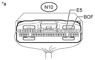
Text in Illustration *a Component with harness connected
(Clearance Warning ECU Assembly)
Measure the resistance according to the value(s) in the table below.
Standard Resistance Tester Connection Condition Specified Condition N10-6 (E5) - Body ground Always Below 1 Ω -
Measure the voltage according to the value(s) in the table below.
Standard Voltage Tester Connection Condition Specified Condition N10-4 (BOF) - Body ground Always 7.2 to 8.8 V
NG
REPLACE CLEARANCE WARNING ECU ASSEMBLY Click here
OK
-
-
CHECK FOR DTC (C1AEC)
-
Clear the DTCs Click here.
-
Check for DTCs Click here.
Result Result Proceed to DTC C1AEC is output and multi-information display indicates open circuit (Front Left, Front Center and Front Right) A DTC C1AEC is output and multi-information display indicates open circuit (Front Center and Front Right) B No DTC is output C
B 
INSPECT NO. 1 ULTRASONIC SENSOR (FLC SENSOR) Click here
C
USE SIMULATION METHOD TO CHECK Click here
A
-
-
CHECK NO. 1 ULTRASONIC SENSOR (FL SENSOR)
-
Remove the No. 1 ultrasonic sensor (FL sensor) Click here.
-
Inspect the No. 1 ultrasonic sensor (FL sensor) Click here.
NG
REPLACE NO. 1 ULTRASONIC SENSOR (FL SENSOR) Click here
OK
-
-
CHECK FOR DTC (C1AEC)
-
Clear the DTCs Click here.
-
Check for DTCs Click here.
Result Result Proceed to DTC C1AEC is output and multi-information display indicates open circuit (Front Left, Front Center and Front Right) A DTC C1AEC is output and multi-information display indicates open circuit (Front Center and Front Right) B No DTC is output C
B
INSPECT NO. 1 ULTRASONIC SENSOR (FLC SENSOR) Click here
C
USE SIMULATION METHOD TO CHECK Click here
A
-
-
REPLACE NO. 1 ULTRASONIC SENSOR (FR SENSOR)
-
Replace the No. 1 ultrasonic sensor (FR sensor) with a normally functioning sensor Click here.
Tech Tips
All of the sensors are interchangeable. To confirm whether a sensor is functioning normally, switch it with a known good sensor from the other end of the vehicle.
NEXT
-
-
CHECK FOR DTC (C1AEC)
-
Clear the DTCs Click here.
-
Check for DTCs Click here.
Result Result Proceed to DTC C1AEC is output and multi-information display indicates open circuit (Front Left, Front Center and Front Right) A DTC C1AEC is output and multi-information display indicates open circuit (Front Center and Front Right) B No DTC is output C
B
REPLACE CLEARANCE WARNING ECU ASSEMBLY Click here
C
END (NO. 1 ULTRASONIC SENSOR [FR SENSOR] WAS DEFECTIVE)
A
-
-
INSPECT NO. 1 ULTRASONIC SENSOR (FLC SENSOR)
-
Remove the No. 1 ultrasonic sensor (FLC sensor) Click here.
-
Inspect the No. 1 ultrasonic sensor (FLC sensor) Click here.
NG
REPLACE NO. 1 ULTRASONIC SENSOR (FLC SENSOR) Click here
OK
-
-
CHECK FOR DTC (C1AEC)
-
Clear the DTCs Click here.
-
Check for DTCs Click here.
Result Result Proceed to No DTC is output A DTC C1AEC is output B
B
INSPECT NO. 1 ULTRASONIC SENSOR (FRC SENSOR) Click here
A 
USE SIMULATION METHOD TO CHECK Click here
-
-
INSPECT NO. 1 ULTRASONIC SENSOR (FRC SENSOR)
-
Remove the No. 1 ultrasonic sensor (FRC sensor) Click here.
-
Inspect the No. 1 ultrasonic sensor (FRC sensor) Click here.
NG
REPLACE NO. 1 ULTRASONIC SENSOR (FRC SENSOR) Click here
OK
-
-
CHECK FOR DTC (C1AEC)
-
Clear the DTCs Click here.
-
Check for DTCs Click here.
Result Result Proceed to No DTC is output A DTC C1AEC is output B
B
REPLACE CLEARANCE WARNING ECU ASSEMBLY Click here
A
USE SIMULATION METHOD TO CHECK Click here
-