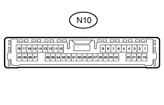
LEXUS PARKING ASSIST-SENSOR SYSTEM TERMINALS OF ECU

-
CLEARANCE WARNING ECU ASSEMBLY
-
Disconnect the N10 connector from the clearance warning ECU assembly.
-
Measure the voltage and resistance according to the value(s) in the table below.
Terminal No. (Symbol) Wiring Color Terminal Description Condition Specified Condition N10-1 (IG) - N10-30 (E) LG - W-B IG power source signal Power switch off Below 1.5 V Power switch on (IG) 11 to 14 V N10-9 (CLSW) - N10-30 (E) SB - W-B Back sonar or clearance sonar switch power source signal Power switch on (IG), back sonar or clearance sonar switch on 11 to 14 V Power switch on (IG), back sonar or clearance sonar switch off Below 1 V N10-30 (E) - Body ground W-B - Body ground Ground Always Below 1 Ω -
Reconnect the N10 connector to the clearance warning ECU assembly.
-
Measure the voltage and resistance, and check for pulses according to the value(s) in the table below.
Terminal No. (Symbol) Wiring Color Terminal Description Condition Specified Condition N10-4 (BOF) - N10-30 (E) R - W-B Power source for front sensor circuit Power switch off Below 1.5 V Power switch on (IG), back sonar or clearance sonar switch on 7.2 to 8.8 V N10-6 (E5) - N10-30 (E) G - W-B Ground for front clearance sonar Always Below 1 Ω N10-8 (SOF) - N10-30 (E) SB - W-B Front sensor communication signal (Front clearance sonar sensor) Hybrid control system starts, back sonar or clearance sonar switch on, reverse (R) selected Pulse generation
(See waveform 1)
N10-15 (CBZ) - N10-30 (E) LG - W-B Clearance warning buzzer signal Power switch off Below 1 V Hybrid control system starts, back sonar or clearance sonar switch on, reverse (R) selected 11 to 14 V N10-16 (EF) - N10-30 (E) L - W-B Ground of clearance warning buzzer When sonar detects obstacle (buzzer sounds) Pulse generation
(See waveform 2)
N10-22 (BOR) - N10-30 (E) GR - W-B Power source for rear sensor circuit Power switch off Below 1.5 V Power switch on (IG), back sonar or clearance sonar switch on 7.2 to 8.8 V N10-23 (E1) - N10-30 (E) W - W-B Ground for rear clearance sonar Always Below 1 Ω N10-24 (SOR) - N10-30 (E) P - W-B Rear sensor communication signal (Rear clearance sonar sensor) Hybrid control system starts, back sonar or clearance sonar switch on, reverse (R) selected Pulse generation
(See waveform 1)
-
Using an oscilloscope, check waveform 1.
-
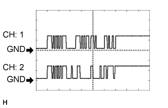
Waveform 1 (Reference)
Item Content Terminal No. (Symbol)
-
CH: 1 N10-8 (SOF) - N10-30 (E)
-
CH: 2 N10-24 (SOR) - N10-30 (E)
Tool Setting 5 V/DIV., 1 msec./DIV. Condition Hybrid control system starts, back sonar or clearance sonar switch on, reverse (R) selected Tech Tips
The waveforms for CH1 and CH2 are same.
-
-
-
Using an oscilloscope, check waveform 2.
-
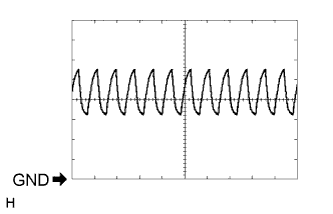
Waveform 2 (Reference)
Item Content Terminal No. (Symbol) N10-16 (EF) - N10-30 (E) Tool Setting 2 V/DIV., 500 μsec./DIV. Vehicle Condition When sonar detects obstacle (buzzer sounds) Tech Tips
The amplitude of the waveform changes according to the set volume.
-
-