MAYDAY SWITCH INSPECTION

-
INSPECT MAP LIGHT ASSEMBLY
-
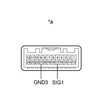
Text in Illustration *a Component without harness connected
(Map Light Assembly)
Measure the resistance according to the value(s) in the table below.
Standard Resistance Tester Connection Condition Specified Condition Y11-17 (SIG1) - Y11- 21 (GND3) Not pressing emergency alert switch 412 Ω Y11-17 (SIG1) - Y11- 21 (GND3) Pressing emergency alert switch 82 Ω If the result is not as specified, replace the map light assembly.
-
Inspect the operation (indicator)
-
Connect 2 dry-cell batteries to the terminals of the map light assembly connector as shown in the illustration and check that the indicators illuminate.
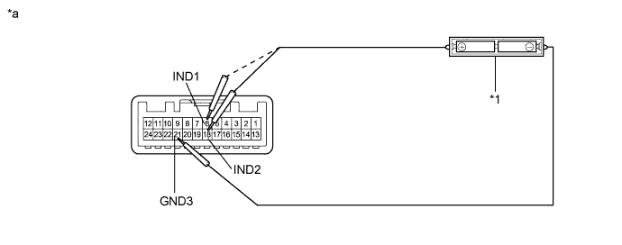
Text in Illustration *1 2 (1.5 V) Dry-cell Batteries - - *a Component without harness connected
(Map Light Assembly)
- - Note
Do not apply a voltage of 3 V or higher to the indicators.
OK Tester Connection Specified Condition Battery positive (+) - Y11-6 (IND1)
Battery negative (-) - Y11-21(GND3)
Help red indicator illuminates Battery positive (+) - Y11-18 (IND2)
Battery negative (-) - Y11-21 (GND3)
Help green indicator illuminates If the result is not as specified, replace the map light assembly.
-
-
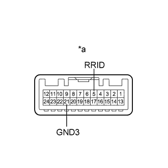
Text in Illustration *a Component without harness connected
(Map Light Assembly)
Connect the battery to the connector terminals of the map light assembly and check that the HELP indicator illuminates.
OK Tester Connection Specified Condition Battery positive (+) - Y11-5 (RRID)
Battery negative (-) - Y11-21 (GND3)
Help indicator illuminates If the result is not as specified, replace the map light assembly.
-