REMOTE TOUCH DISASSEMBLY

-
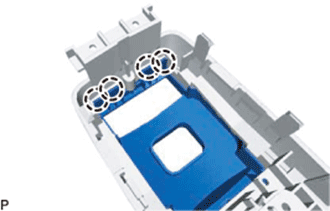
REMOVE COVER
-
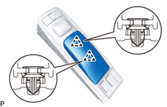
Detach the 2 clips and remove the cover.
-
-
REMOVE SWITCH KNOB
-
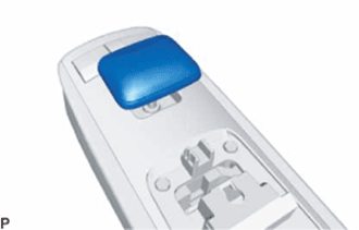
Remove the switch knob upward.
-
-
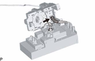
REMOVE REMOTE OPERATION BOARD
-
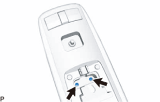
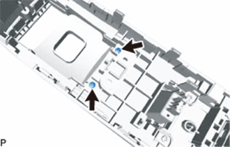
Remove the 2 screws.
-
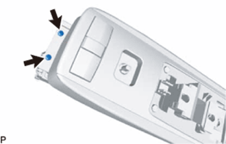
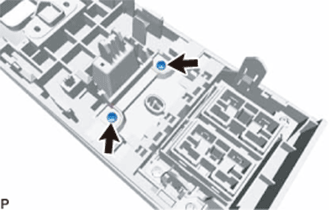
Remove the 2 screws.
-
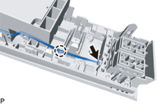
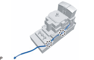
Disconnect the connector, remove the wire harness from the claw, and then remove the remote operation board.
-
-
REMOVE INTEGRATION PANEL SUB-ASSEMBLY
-
Remove the 2 screws.
-
Remove the 2 screws.
-
Remove the 4 screws.
-
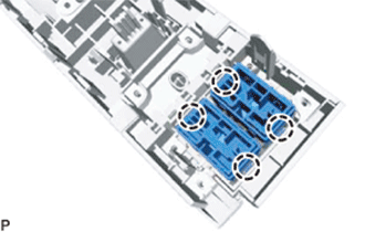
Detach the 4 claws and remove the cover assembly RH from the integration panel sub-assembly.
-
-
REMOVE RH COVER ASSEMBLY
-
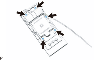
Detach the 4 claws and remove the 2 switches.
Tech Tips
A switch hole cover is installed if there is no switch.
-
-
REMOVE REMOTE OPERATION SWITCH
-
Detach the the wire harness from the claws.
-
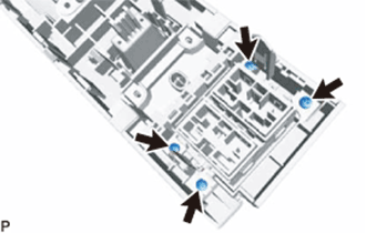
Remove the 5 screws.
-
Separate the remote operation switch from the remote operation board and disconnect the connector on the underside to remove the remote operation switch.
Note
When separating the remote operation switch from the remote operation board, do not excessively pull it, as the connector is still connected.
-