NAVIGATION SYSTEM Display Signal Circuit between Multi-display and Radio Receiver
DESCRIPTION
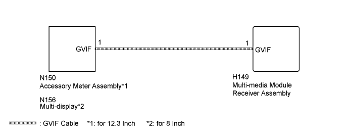
The display image signal from the multi-media module receiver assembly is sent to the accessory meter assembly (for 12.3 Inch) or multi-display (for 8 Inch) using a GVIF cable.
WIRING DIAGRAM
INSPECTION PROCEDURE
PROCEDURE
-
CHECK GVIF CABLE CONNECTOR
-
Check if the GVIF cable connector between the multi-media module receiver assembly and the accessory meter assembly (for 12.3 Inch) or multi-display (for 8 Inch) has any connection problems Click here.
-
Check that the screen display is normal.
OK Screen display is normal.
NG 
CHECK ACCESSORY METER ASSEMBLY OR MULTI-DISPLAY Click here
OK 
USE SIMULATION METHOD TO CHECK Click here
-
-
CHECK ACCESSORY METER ASSEMBLY OR MULTI-DISPLAY
-
Replace the accessory meter assembly (for 12.3 Inch) or multi-display (for 8 Inch) Click here.
-
Check that the screen display is normal.
OK Screen display is normal.
NG 
PROCEED TO NEXT SUSPECTED AREA SHOWN IN PROBLEM SYMPTOMS TABLE Click here
OK
END (ACCESSORY METER ASSEMBLY OR MULTI-DISPLAY IS DEFECTIVE)
-