NAVIGATION SYSTEM, Diagnostic DTC:B15D6

| DTC Code | DTC Name |
|---|---|
| B15D6 | Display Disconnected |
DESCRIPTION
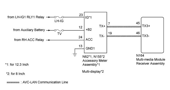
The accessory meter assembly (for 12.3 Inch) or multi-display (for 8 Inch) and multi-media module receiver assembly are connected by an AVC-LAN communication line.
When an AVC-LAN communication error occurs between the multi-media module receiver assembly and accessory meter assembly (for 12.3 Inch) or multi-display (for 8 Inch), these DTCs will be stored.
| DTC Code | DTC Detection Condition | Trouble Area |
|---|---|---|
| B15D6* | A device that is listed in the AVC-LAN connected device record of the master unit is missing. |
|
-
*1: for 12.3 Inch
-
*2: for 8 Inch
Tech Tips
-
*: Even if no fault is present, this DTC may be stored depending on the auxiliary battery condition or hybrid control system start voltage.
-
The multi-media module receiver assembly is the master unit.
WIRING DIAGRAM
INSPECTION PROCEDURE
Note
-
Inspect the fuses for circuits related to this system before performing the following inspection procedure.
-
Depending on the parts that are replaced during vehicle inspection or maintenance, performing initialization, registration or calibration may be needed. Refer to Precaution for Navigation System Click here.
PROCEDURE
-
CLEAR DTC
-
Clear the DTCs Click here.
NEXT 
-
-
CHECK DTC
-
Recheck for DTCs and check if the same DTC is output again Click here.
OK No DTCs are output
NG 
CHECK VEHICLE TYPE Click here
OK 
USE SIMULATION METHOD TO CHECK Click here
-
-
CHECK VEHICLE TYPE
-
Check the vehicle type.
Result Result Proceed to for 12.3 Inch A for 8 Inch B
B
CHECK HARNESS AND CONNECTOR (MULTI-DISPLAY - BATTERY AND BODY GROUND) Click here
A
-
-
CHECK HARNESS AND CONNECTOR (ACCESSORY METER ASSEMBLY - BATTERY AND BODY GROUND)
-
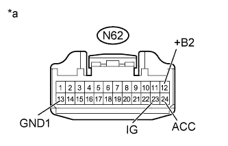
Text in Illustration *a Front view of wire harness connector
(to Accessory Meter Assembly)
Disconnect the accessory meter assembly connector.
-
Measure the resistance according to the value(s) in the table below.
Standard Resistance Tester Connection Condition Specified Condition N62-13 (GND1) - Body ground Always Below 1 Ω -
Measure the voltage according to the value(s) in the table below.
Standard Voltage Tester Connection Switch Condition Specified Condition N62-12 (+B2) - N62-13 (GND1) Power switch off 11 to 14 V N62-23 (IG) - N62-13 (GND1) Power switch on (IG) 11 to 14 V N62-24 (ACC) - N62-13 (GND1) Power switch on (ACC) 11 to 14 V
NG 
REPAIR OR REPLACE HARNESS OR CONNECTOR
OK
-
-
INSPECT MULTI-MEDIA MODULE RECEIVER ASSEMBLY
-
Remove the multi-media module receiver assembly Click here.
-
Measure the resistance according to the value(s) in the table below.
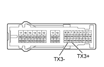
Standard Resistance Tester Connection Condition Specified Condition 45 (TX3+) - 46 (TX3-) Always 60 to 80 Ω
NG
REPLACE MULTI-MEDIA MODULE RECEIVER ASSEMBLY Click here
OK
-
-
CHECK HARNESS AND CONNECTOR (MULTI-MEDIA MODULE RECEIVER ASSEMBLY - ACCESSORY METER ASSEMBLY)
-
Disconnect the N164 multi-media module receiver assembly connector.
-
Disconnect the N62 accessory meter assembly connector.
-
Measure the resistance according to the value(s) in the table below.
Standard Resistance Tester Connection Condition Specified Condition N164-45 (TX3+) - N62-7 (TX+) Always Below 1 Ω N164-46 (TX3-) - N62-19 (TX-) Always Below 1 Ω N164-45 (TX3+) - Body ground Always 10 kΩ or higher N164-46 (TX3-) - Body ground Always 10 kΩ or higher
NG
REPAIR OR REPLACE HARNESS OR CONNECTOR
OK
-
-
REPLACE ACCESSORY METER ASSEMBLY
-
Replace the accessory meter assembly with a new or normally functioning one Click here.
NEXT
-
-
CLEAR DTC
-
Clear the DTCs Click here.
NEXT
-
-
CHECK DTC
-
Recheck for DTCs and check if the same DTC is output again Click here.
OK No DTCs are output
NG
REPLACE MULTI-MEDIA MODULE RECEIVER ASSEMBLY Click here
OK
END (ACCESSORY METER ASSEMBLY IS DEFECTIVE)
-
-
CHECK HARNESS AND CONNECTOR (MULTI-DISPLAY - BATTERY AND BODY GROUND)
-
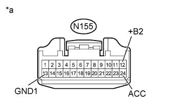
Text in Illustration *a Front view of wire harness connector
(to Multi-display)
Disconnect the multi-display connector.
-
Measure the resistance according to the value(s) in the table below.
Standard Resistance Tester Connection Condition Specified Condition N155-13 (GND1) - Body ground Always Below 1 Ω -
Measure the voltage according to the value(s) in the table below.
Standard Voltage Tester Connection Switch Condition Specified Condition N155-12 (+B2) - N155-13 (GND1) Power switch off 11 to 14 V N155-24 (ACC) - N155-13 (GND1) Power switch on (ACC) 11 to 14 V
NG
REPAIR OR REPLACE HARNESS OR CONNECTOR
OK
-
-
INSPECT MULTI-MEDIA MODULE RECEIVER ASSEMBLY
-
Remove the multi-media module receiver assembly Click here.
-
Measure the resistance according to the value(s) in the table below.
Standard Resistance Tester Connection Condition Specified Condition 45 (TX3+) - 46 (TX3-) Always 60 to 80 Ω
NG
REPLACE MULTI-MEDIA MODULE RECEIVER ASSEMBLY Click here
OK
-
-
CHECK HARNESS AND CONNECTOR (MULTI-MEDIA MODULE RECEIVER ASSEMBLY - MULTI-DISPLAY)
-
Disconnect the N164 multi-media module receiver assembly connector.
-
Disconnect the N155 multi-display connector.
-
Measure the resistance according to the value(s) in the table below.
Standard Resistance Tester Connection Condition Specified Condition N164-45 (TX3+) - N155-7 (TX+) Always Below 1 Ω N164-46 (TX3-) - N155-19 (TX-) Always Below 1 Ω N164-45 (TX3+) - Body ground Always 10 kΩ or higher N164-46 (TX3-) - Body ground Always 10 kΩ or higher
NG
REPAIR OR REPLACE HARNESS OR CONNECTOR
OK
-
-
REPLACE MULTI-DISPLAY
-
Replace the multi-display with a new or normally functioning one Click here.
NEXT
-
-
CLEAR DTC
-
Clear the DTCs Click here.
NEXT
-
-
CHECK DTC
-
Recheck for DTCs and check if the same DTC is output again Click here.
OK No DTCs are output
NG
REPLACE MULTI-MEDIA MODULE RECEIVER ASSEMBLY Click here
OK
END (MULTI-DISPLAY IS DEFECTIVE)
-